MX3500N SCANNER SECTION C – 3
3. Disassembly and assembly
A. Optical system
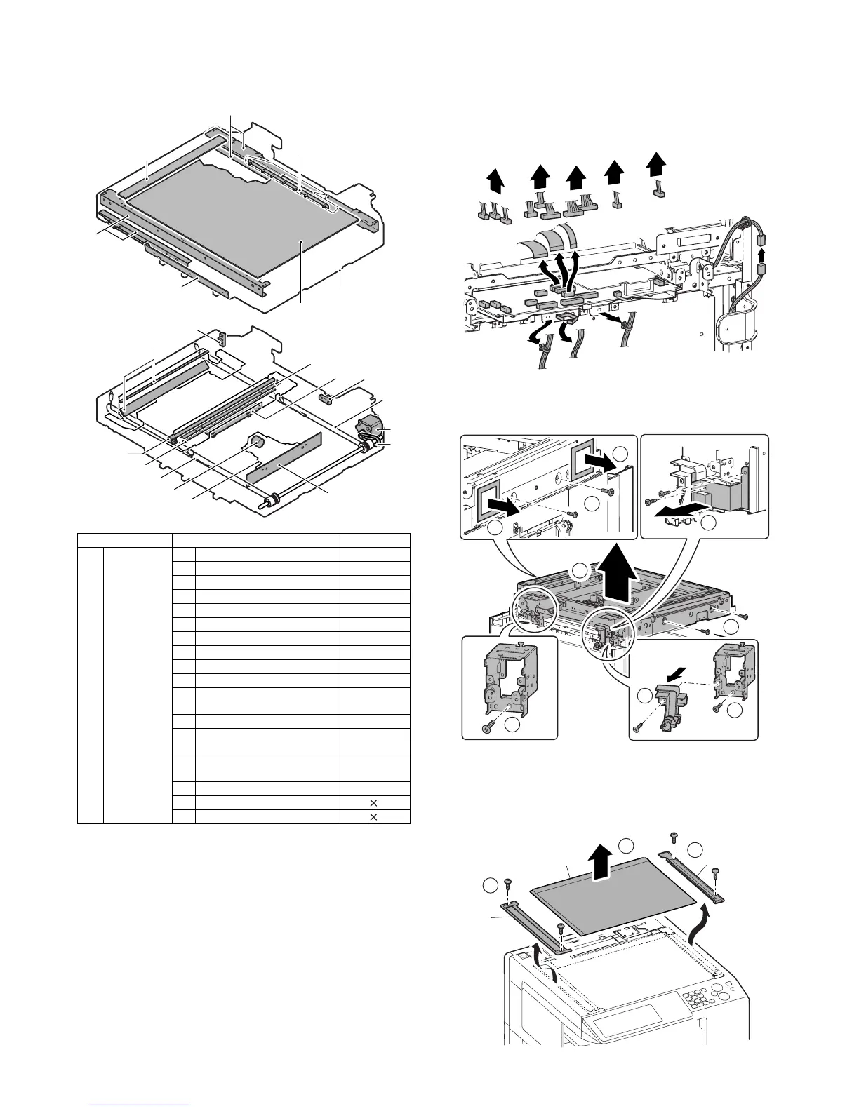
(1) Scanner unit
1) Remove the upper cabinet rear cover and the upper cabinet
rear.
2) Remove the table glass and the SPF glass.
3) Remove the upper cabinet right and the upper cabinet left.
4) Disconnect the connector and remove the snap band.
5) Remove the mylar. Remove the screws, and the ground sheet.
Remove the screw, and the I/F cable holder unit. Remove the
screws, and remove the scanner unit.
a. Table glass
b. SPF glass
1) Remove the SPF glass (A). Remove the glass holder (B) and
the table glass (C).
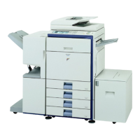
Unit Parts Maintenance
(1) Scanner unit a Table glass {
bSPF glass {
c Lens {
d CCD {
eReflector {
f Mirrors {
gLamp {
h CL inverter PWB
i CCD unit
j Scanner motor
k Scanner home position
sensor
l Original cover SW
m Document detection light
receiving PWB
n Document detection light
emitting PWB
o Rails ✩
p Drive wire
qDrive belt
(1)-a
(1)-o
(1)-b
(1)-p
(1)-h
(1)-g
(1)-p
(1)-f
(1)-d
(1)-f
(1)-e
(1)-c
(1)-o
(1)-m
(1)-n
(1)-l
(1)-j
(1)-k
(1)-q
(1)-i
(1)
4
4
4
1
1
5
3
4
2
1
A
3
B
C
2
 Loading...