MX-M700N SIMULATION 7 – 31
40-2
Purpose
Adjustment
Function (Purpose)
Used to adjust the manual paper feed tray
paper width detector detection level.
Section
Paper feed
Operation/Procedure
1) Open the manual paper feed guide to the maximum width posi-
tion.
2) Select MAX. POSITION with 10-key.
3) Press the [START] key.
The max. width detection level is recognized.
4) Press the [SYSTEM SETTINGS] key.
5) Set the manual paper feed guide to the width for the A4R size.
6) Select POSITION 1 with 10-key.
7) Press the [START] key.
The A4R width detection level is recognized.
8) Press the [SYSTEM SETTINGS] key.
9) Set the manual paper feed guide to A5R size width.
10) Select POSITION 2 with 10-key.
11) Press the [START] key.
The A5R width detection level is recognized.
12) Press the [SYSTEM SETTINGS] key.
13) Open the manual paper feed guide to the minimum width posi-
tion.
14) Select MIN. POSITION with 10-key.
15) Press the [START] key.
The minimum width detection level is recognized.
When each of the above operations has been completed, the
"COMPLETE" message appears; when any of the operations has
failed, the "ERROR" message appears.
40-7
Purpose
Adjustment/Setup
Function (Purpose)
Used to enter the manual paper feed tray
paper width adjustment value.
Section
Paper feed
Operation/Procedure
1) Select the number corresponding to the set item with 10-key.
2) Press the [START] key.
3) Enter the set value with 10-key.
4) Press the [START] key.
40-11
Purpose
Operation test/Check
Function (Purpose)
Used to check the multi-purpose tray width
detection adjustment value.
Section
Paper feed
Operation/Procedure
The sensor and detector operation conditions are displayed.
The active sensors and detectors are highlighted. The paper width
detection level is also displayed.
40-12
Purpose
Adjustment/Setup
Function (Purpose)
Used to check the multi-purpose tray width
detection adjustment value.
Section
Paper feed
Operation/Procedure
1) Open the paper feed tray 3 paper feed guide to the max. width
position.
2) Select MAX. POSITION with 10-key.
3) Press the [START] key.
The max. width detection level is recognized.
4) Press the [SYSTEM SETTINGS] key.
5) Open the paper feed tray 3 paper feed guide to the min. width
position.
6) Select MIN. POSITION with 10-key.
7) Press the [START] key.
The minimum width detection level is recognized.
If the above procedures are not completed normally, "ERROR" is
displayed. If completed normally, "COMPLETE" is displayed.
1 MAX. POSITION Max. position
2 POSITION 1 Adjustment point 1
3 POSITION 2 Adjustment point 2
4 MIN. POSITION Min. position
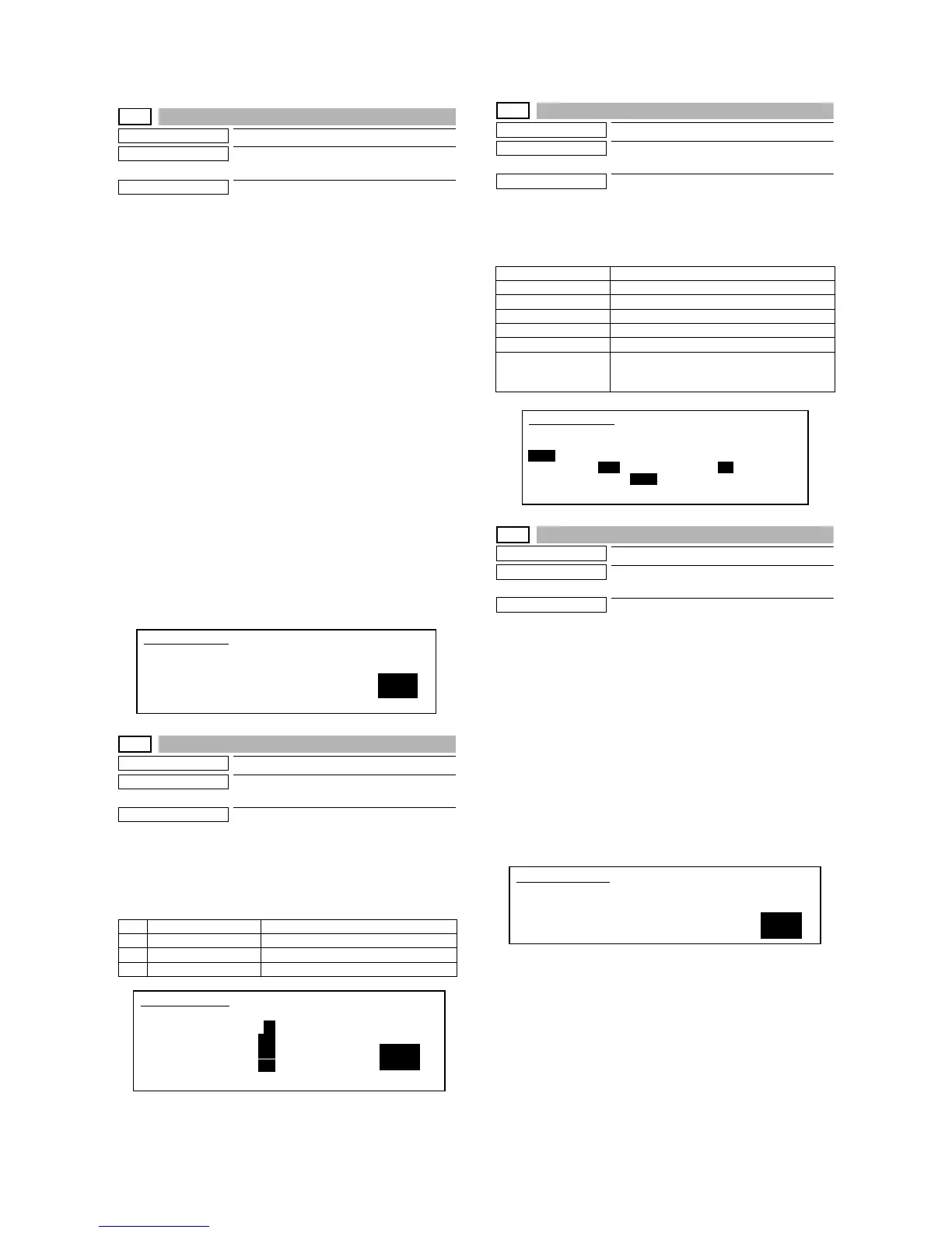
SIMULATION 40-2
BYPASS TRAY ADJUSTMENT. SELECT 1-4, AND PRESS START.
1. MAX. POSITION
2. POSITION 1
3. POSITION 2
4. MIN. POSITION
1
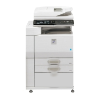
SIMULATION 40-7
1
BYPASS TRAY VALUE SETTING. SELECT 1-4, AND PRESS START.
1. MAX. POSITION : 72
2. POSITION 1 : 380
3. POSITION 2 : 710
4. MIN. POSITION : 804
M1SS1 Tray 3 size detection 1
M1SS2 Tray 3 size detection 2
M1SS3 Tray 3 size detection 3
M1SS4 Tray 3 size detection 4
TRAY3_WIDTH Tray 3 guide plate position
TRAY3_AD Tray 3 width detection volume output AD value
Tray3 width size (Tray 3 width direction detection size is
displayed.) A4/A3, 11X, B5/B4, 8.5X, A4R, B5R,
A5R, 5.5X, 7.25X, EXTRA
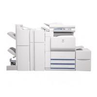
SIMULATION 40-11
TRAY3 SENSOR CHECK..
M1SS1 M1SS2 M1SS3 M1SS4
TRAY3_WIDTH: 2100 TRAY3_AD: 600
(Tray3 width size: A4/A3)
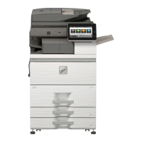
SIMULATION 40-12
TRAY3 ADJUSTMENT. SELECT 1-2, AND PRESS START.
1. MAX. POSITION
2. MIN. POSITION
1