1. Introduction
These installation guidelines summarize the preparations that the customer should
make to smooth the installation of the delivered GCMS-QP2010.
Please follow these guidelines to ensure safety, reliable analysis, and long use of the
instrument.
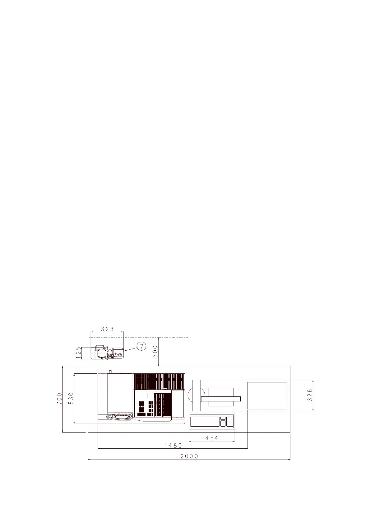
2. Installation example
The diagram on the next page shows the example of a standard GCMS-QP2010
configuration installed on a table. (The oil rotary pump i is located on the floor.)
Leave a space of at least 300mm between the rear edge of the table and the wall for
the following reasons:
(1) to position the oil rotary pump;
(2) for the discharge of hot air during column-oven cooling;
(3) for maintenance.
Also, for inspection and maintenance purposes, leave a space of at least 400mm at
the left of the table.
3. Installation room conditions
Temperature Guaranteed within specification 18 to 28
M
C (constant)
Guaranteed operation 15 to 35
M
C (*)
Choose a location not subject to direct sunlight or air-conditioner
output.
During normal analysis, the instrument generates approximately
1.5kW.
(*) The instrument will operate across the guaranteed operation
temperature range above. However, operation for long periods
outside the temperatures guaranteed within specification can
reduce the instrument life and have other adverse effects on the
instrument.
Humidity 40% to 70% (no condensation)
Installation location Sturdy table approx. 2000mm (W) x 700mm (D), able to easily
support 110kg. Leave at least 300mm space behind the table.
Others The room where the instrument is installed should be as free as
possible of harmful elements, such as dust, vibrations,
electromagnetic fields, and corrosive gas.
Do not use the instrument in an explosive-gas environment.

 Loading...


