48
7. Make coarse adjustment of the lens voltages (Lenses 1 to 4) to maximize the m/z=69
peak intensity. Adjust the detector voltage (EM) into the range 100000 to 200000.
8. Press the end measurement button when the adjustment is complete.
Adjustment of RF power-supply trimmers VR1 (RF) and VR2 (M/Z)
* Remove the rear cover before adjusting the RF power-supply trimmers.
1. Select "Adjust RF trimmers"
from "Adjust Resolution" in the Tools menu.
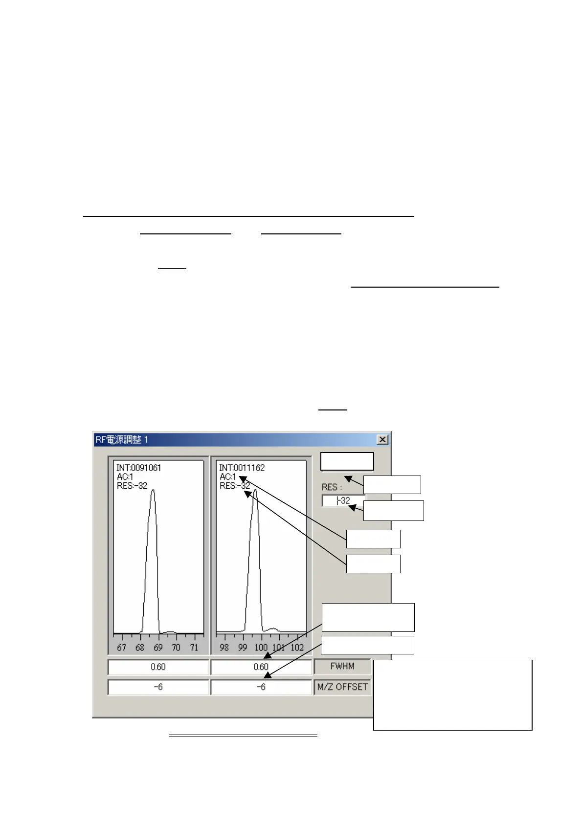
2. The RF Power Supply Adjustment 1 window opens. (Fig. 2)
3. Press the Adjust
button to display the m/z69, 100 peaks, peak full widths at half
maximum (FWHM), and the peak m/z offsets in the RF Power Supply Adjustment 1
window.
4. Adjust VR1 (RF) and VR2 (M/Z) to set FWHM=0.6 and identical M/Z OFFSET values for
each peak, as follows:
4.1 Adjust VR1 until both FWHM values are identical.
4.2 Use the RES set value to adjust the FWHM values to 0.6.
4.3 Adjust VR2 until both M/Z OFFSET values are identical.
5. When the adjustments are complete, press the Adjust
button to end measurements and
close the window.
Fig. 2 RF Power Supply Adjustment 1 Window
Adjust button
RES set value
Peak m/z offset
Peak full width at half
maximum (FWHM)
AC value
RES value
Adjustment range
FWHM 0.6±0.02 AMU
OFFSET Difference 2 within
ADJUST

 Loading...


