56
<Indication>
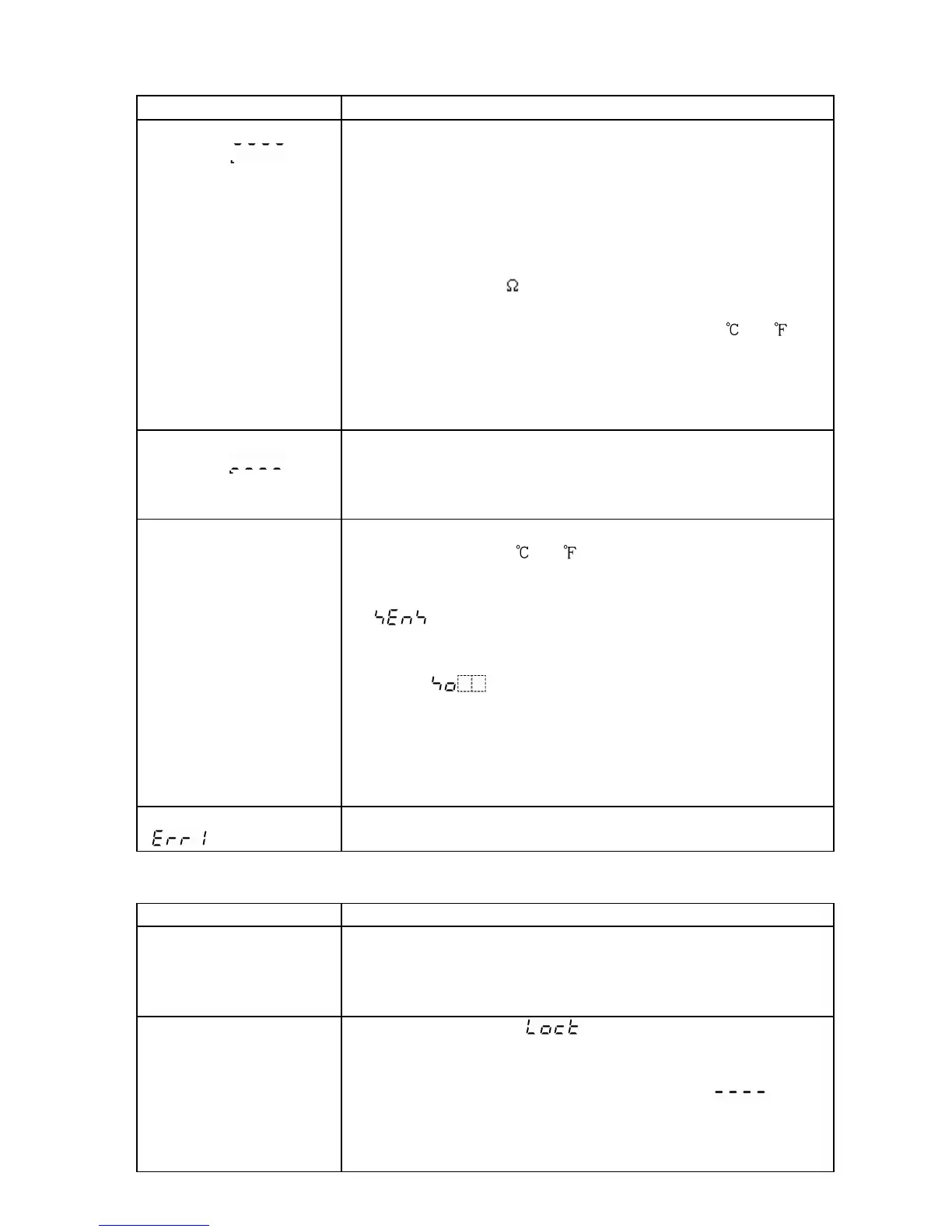
Problem Presumed cause and solution
The PV display is
blinking [ ].
• Thermocouple or RTD is burnt out.
[Thermocouple]
If the input terminal of the instrument is shorted,
and if nearby room temperature is indicated,
the instrument is probably normal and the sensor
may be burnt out.
[RTD]
If approx. 100 of resistance is connected to the
input terminals between A-B of the instrument and
between B-B is shorted, and if nearby 0 (32 ) is
indicated, the instrument is probably normal and the
sensor may be burnt out.
• Lead wire of thermocouple or RTD is not securely
mounted to the instrument terminals.
The PV display is
blinking [ ].
• Polarity of thermocouple or compensating lead wire
is reversed.
• Codes (A, B, B) of RTD do not agree with the
instrument terminals.
If indication
of PV display
is abnormal or
unstable.
• Designation of the sensor input is improper.
• Temperature unit ( or ) is mistaken.
Set the sensor type which is the same as users’ and
the temperature unit from the Input type selection
[ ]. (p.16)
• Sensor correction value is unsuitable.
Set the value properly from the Sensor correction
setting [ ] in Auxiliary function setting mode 1.
(pp.31, 41, 42)
• AC may be leaking into thermocouple or the RTD
circuit.
• There may be equipment nearby producing an
inductive fault or noise near the controller.
PV display indicates
[ ].
• Internal memory is defective.
Make inquiries to Shinko Technos or our dealers.
<Keypad operation>
Problem Presumed cause and solution
It is impossible to
select program pattern
number.
• The program control is running.
Change the mode.
The program pattern number can be selected in the
program standby mode.
If settings or
selections are
impossible.
• Setting value lock [ ] is designated from the
Setting value lock selection in Auxiliary function setting
mode 1.
Release the lock designation and set to [ ].
(p.31)
• PID auto-tuning is performing.
Cancel the tuning if necessary. (p.28)