Operating Instructions Chapter 4
C 4000 Standard/Advanced
8 009 861/OE59/19-11-04 © SICK AG • Industrial Safety Systems • Germany • All rights reserved
23
Configurable functions
The connection can signal one of the following states:
Assignment Possible uses
Contamination Eases diagnostics in case of soiled front screen
OSSD status with
delay of [s]
Signals the status of the switching outputs. If the safety light
curtain switches to red, then it signals the status immediately. If
it switches to green, then it signals the status only after an
adjustable delay in the range from 0.1 to 3.0 seconds.
Status of the
emergency stop
Signal is present if the button connected to the emergency stop
input on the C 4000 has been pressed.
Protective field
unoccupied
Signal is active if no invalid access is in effect. I.e. the protective
field must be unoccupied in protective operating mode.
Device symbol C 4000 Host (receiver), context menu Configuration draft, Edit, file card
General, option Assignment of the output signal.
The electrical connection of a PLC/controller to the output signal is described in chapter
6.9 “ Output signal (ADO) ” on page 54.
4.6 Beam coding
If several safety light curtains operate in close proximity to each other, the sender beams
of one system may interfere with the receiver of another system. With code 1 or 2 activat-
ed, the receiver can distinguish the beams designated for it from other beams. The follow-
ing settings are available: non-coded, code 1 and code 2.
Use different beam codings if the systems are mounted in close proximity!
Systems mounted in close proximity to each other must be operated with different beam
codings (code 1 or code 2). If this precaution is neglected, the system may be impaired in
its protective function by the beams from the neighbouring system and so change to the
unsafe state. This would mean that the operator is at risk.
$ Beam coding increases the availability of the protected machine. Beam coding also en-
hances the resistance to optical interference such as weld sparks or) similar.
$ In a cascaded system the host and guest always have the same beam coding. There is
no mutual interference.
$ Beam coding will increase the response time of the system. This will also change the
required safety distance. Instructions can be found in chapter 5.1 “Determining the
safety distance” on page 37.
$ After activating the system, sender and receiver will briefly display the coding.
$ Beam coding is only possible on systems with a maximum total of 405 beams.
Device symbol C 4000 Host (receiver) or C 4000 Host (sender), context menu Configura-
tion draft, Edit, file card General, option Beam coding.
Tab. 5: Possible configu-
ration for the output signal
!
%
WARNING
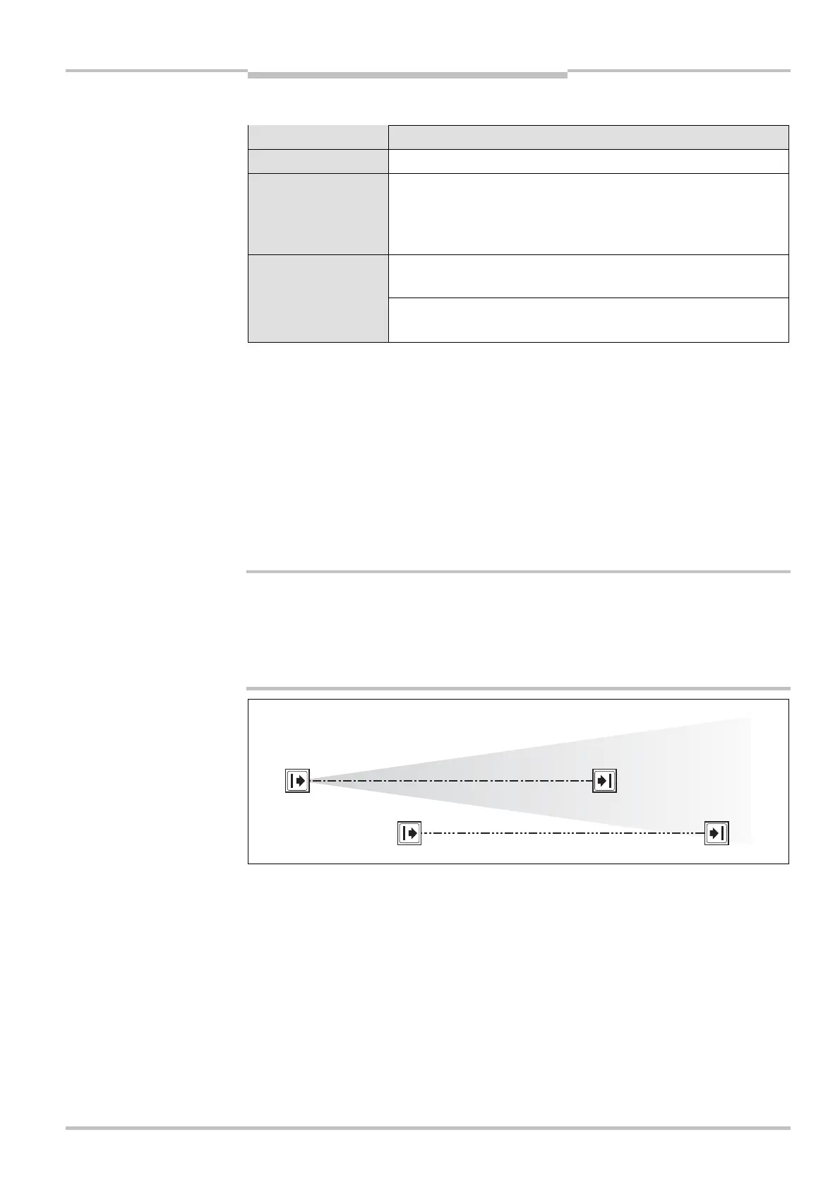
Fig. 9: Schematic layout o
the beam coding
Notes
!
Code 1
Code 2