Chapter 10 Operating Instructions
C 4000 Standard/Advanced
64 © SICK AG • Industrial Safety Systems • Germany • All rights reserved 8 009 861/OE59/19-11-04
Fault diagnosis
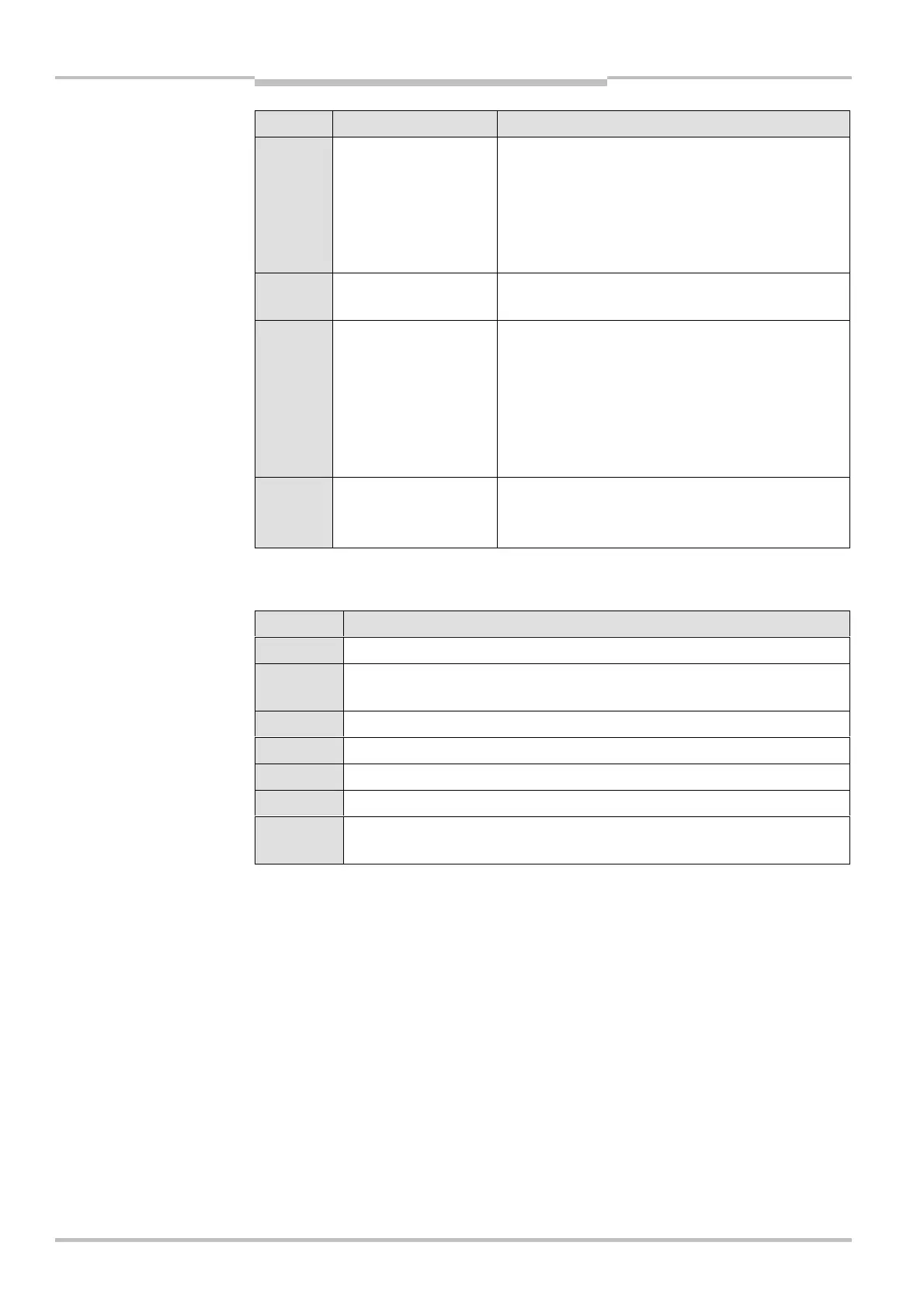
Display Possible cause Remedying the error
;O, Communication in
cascaded system
failed
Verify the configuration of the system using the
CDS (Configuration & Diagnostic Software).
Retransfer the corrected configuration to the
system.
Check the connection between the cascaded
devices. If necessary, replace defective cables.
;O0 Supply voltage too low Check the supply voltage and the power supply. If
necessary, replace defective components.
;O> Fault in PSDI mode Verify the configuration of the system using the
CDS (Configuration & Diagnostic Software).
Retransfer the corrected configuration to the
system.
Check the switch for the machine cycle contacts.
Ensure that these are correctly connected and
configured. Replace this if necessary.
>
Malfunction of a
device connected
via EFI
Perform a fault diagnosis of the device connected
to the C 4000.
10.5 Status indicators on the C 4000
Display Meaning
, Yellow Supply voltage o.k.
6 System error. Disconnect the supply voltage to the C 4000 for at least
3 seconds. If the problem persists, replace the unit.
= The device is in the test mode.
B Non-coded operation (only after switching on)
% Operation with code 1 (only after switching on)
$ Operation with code 2 (only after switching on)
Other
displays
All other displays are error messages.
Tab. 22: Status indicators of
the sender