Chapter 3 Operating Instructions
C 4000 Standard/Advanced
16 © SICK AG • Industrial Safety Systems • Germany • All rights reserved 8 009 861/OE59/19-11-04
Product description
3.4 Status indicators
The LEDs and the 7-segment displays of the sender and the receiver signal the operational
status of the C 4000.
The depiction of numbers on the 7-segment display can be rotated by 180° with the aid of
the CDS (Configuration & Diagnostic Software). In this case the point on the 7-segment
display goes out:
$ Point visible: The bottom edge of the numbers on the 7-segment display is pointing
towards the configuration connection.
$ Point not visible: The bottom edge of the numbers on the 7-segment display is pointing
towards the LED display.
Device symbol C 4000 Host (receiver) or C 4000 Host (sender), context menu Configura-
tion draft, Edit, option 7-segment display of the related device.
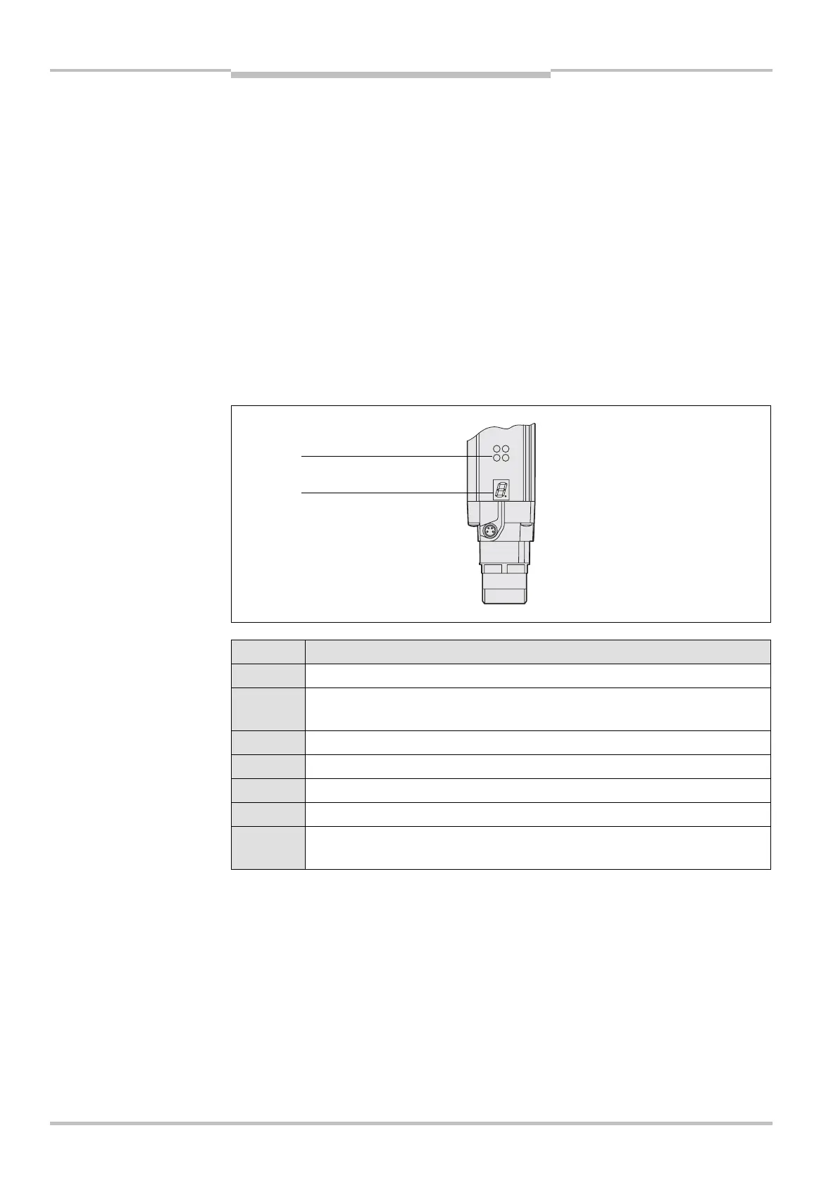
3.4.1 Status indicators of the sender
Display Meaning
, Yellow Supply voltage OK
6 System error. Disconnect the supply voltage to the C 4000 for at least
3 seconds. If the problem persists, replace the unit.
= The device is in the test mode.
B Non-coded operation (only after switching on)
% Operation with code 1 (only after switching on)
$ Operation with code 2 (only after switching on)
Other
displays
All other displays are error messages. Please refer to chapter “Fault
diagnosis” on page 61.
Note
!
Fig. 5: Status indicators of
the sender
Tab. 2: Status indicators o
the sender
Yellow
7-segment display