Chapter 6 Operating Instructions
C 4000 Standard/Advanced
54 © SICK AG • Industrial Safety Systems • Germany • All rights reserved 8 009 861/OE59/19-11-04
Electrical installation
6.8 Key-operated switch for bypass
The bypass function may only be activated by a key-operated switch with an automatic
reset and two levels or by two input signals that are independent of each other, e.g.
two position switches.
The key-operated switch for bypass is connected to the same connections as the
emergency stop, instead of the emergency stop. You can also design it as equivalent (N/C,
N/C) or complementary (N/O, N/C). See Section 6.7 "Emergency stop" on Page 53.
Mount the key-operated switch for bypass in such a way that the hazardous point is
completely visible when the key-operated switch is used.
$ The key-operated switch for bypass must have volt-free contacts.
$ When you connect the key-operated switch for bypass to the C 4000, you can only connect
a teach-in key-operated switch directly to the UE 402. An emergency stop can then no
longer be connected, as it requires the same connections.
$ You must configure the switching mode of the key-operated switch for bypass to comply
with the selected switch type (N/C, N/O or N/O, N/O) with the aid of the CDS:
Device symbol C 4000 Host (receiver), context menu Configuration draft, Edit, selection
System, General tab, option Key-operated switch for bypass.
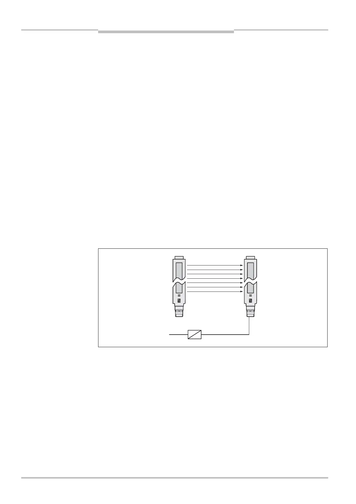
6.9 Output signal (ADO)
Pin 7 on the system connector is a output signal (ADO). You can use this output for a relay
or a PLC.
If you connect the output signal, then you must configure it with the aid of the CDS prior to
commissioning. Details can be found in chapter 4.5 “Output signal (ADO)” on page 22.
Device configuration after replacement!
If you replace a safety light curtain on which the output signal (ADO) is connected, then you
must transfer the configuration to the device again. It is not sufficient to make the elec-
trical connections, because new devices are supplied ex factory with the output signal
deactivated.
Notes
!
Fig. 35: Connection to the
output signal
!
Note
#
"
Pin 7
0 V D
C