Chapter 12 Operating Instructions
C 4000 Standard/Advanced
88 © SICK AG • Industrial Safety Systems • Germany • All rights reserved 8 009 861/OE59/19-11-04
Ordering information
12.4 Additional front screen (weld spark guard)
$ Two additional front screens (weld spark guards) supplied for each part number.
$ The additional front screen fits both on the sender and on the receiver.
$ The additional front screen may be used only if the curved enclosure side is accessible.
$ An additional front screen reduces the scanning range of the system by 8)%. If sender
and receiver each use an additional front screen, the scanning range will be reduced by
16)%.
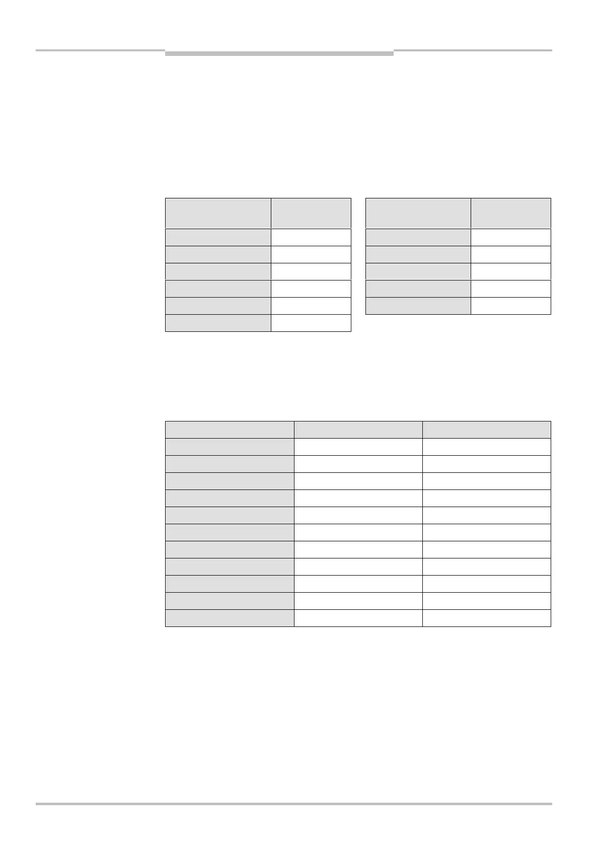
Protective field height
[mm]
Part number Protective field height
[mm]
Part number
300 2 022 412 1200 2 022 418
450 2 022 413 1350 2 022 419
600 2 022 414 1500 2 022 420
750 2 022 415 1650 2 022 421
900 2 022 416 1800 2 022 422
1050 2 022 417
12.5 Deflector mirror
12.5.1 Deflector mirror PNS 75 for protective field width 0 … 8 m (total)
Protective field height [mm] Type number Part number
300 PNS 75-034 1 019 414
450 PNS 75-049 1 019 415
600 PNS 75-064 1 019 416
750 PNS 75-079 1 019 417
900 PNS 75-094 1 019 418
1050 PNS 75-109 1 019 419
1200 PNS 75-124 1 019 420
1350 PNS 75-139 1 019 421
1500 PNS 75-154 1 019 422
1650 PNS 75-169 1 019 423
1800 PNS 75-184 1 019 424
Dimensional drawing see Fig. 43 on page 77. Effect on the scanning range see Tab. 7 on
page 24.
Notes
Tab. 44: Part numbers
additional front screen (weld
spark guard)
Tab. 45: Part numbers
deflector mirror PNS 75