Chapter 4 Operating Instructions
C 4000 Standard/Advanced
24 © SICK AG • Industrial Safety Systems • Germany • All rights reserved 8 009 861/OE59/19-11-04
Configurable functions
4.7 Scanning range
Match the scanning range with the protective field width!
The scanning range of the system (host, guest 1 and guest 2) must be adapted to the
width of the protective field.
$ If the scanning range is set too low, the light curtain may not switch to green.
$ If the scanning range is too great, the light curtain may malfunction. This would mean
that the operator is at risk.
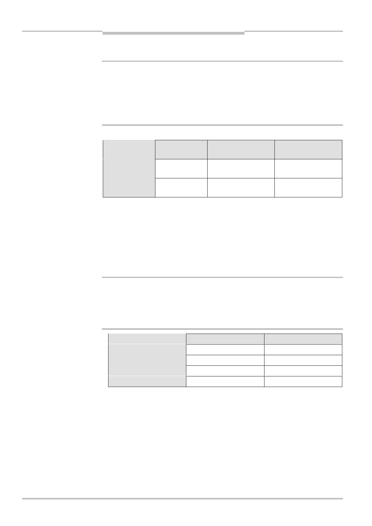
The available settings depend on the physical resolution of the system:
Physical resolution Selectable
scanning ranges
Scanning range with 1
additional front screen
Scanning range with 2
additional front screens
14 mm 0-2.5 m
2-6 m
0-2.3 m
1.8-5.5 m
0-2.1 m
1.7-5 m
20 mm, 30 mm,
40 mm
0-6 m
5-19 m
0-5.5 m
4.6-17.4 m
0-5 m
4.2-16 m
Device symbol C 4000 Host (receiver), context menu Configuration draft, Edit, file card
Host or Guest, option Scanning range [m].
$ If you are using the additional front screen (see page 88) available as an accessory, the
overall scanning range will be reduced by 8)%.
$ The deflector mirrors available as accessories (see page 77f.) reduce the useable
scanning range as a function of the number of deflector mirrors in the light path (see
Tab. 7). When using deflector mirrors, you must configure the light curtain for a long
scanning range.
Do not use deflector mirrors if the formation of droplets or heavy contamination of the
deflector mirrors is to be expected.
The formation of droplets of heavy contamination can be detrimental to the reflection
behaviour. The protective function of the system will be affected and the system will thus
become unsafe. This would mean that the operator is at risk.
Deflector mirror 14 mm 20, 30 or 40 mm
1 × PNS 75 5.4 m 8.0 m
2 × PNS 75 4.8 m 8.0 m
1 × PNS 125 5.4 m 17.0 m
2 × PNS 125 4.8 m 15.2 m
The information in the table relates to 90° beam deflection per mirror and a protective
field height of 900 mm. If you need more advice on mirror applications, please get in
touch with your contact at SICK.
%
WARNING
Tab. 6: Physical resolution
and scanning range
!
Notes
%
WARNING
Tab. 7: Scanning range when
using 1 or 2 deflector mirrors