Operating Instructions Chapter 6
C 4000 Standard/Advanced
8 009 861/OE59/19-11-04 © SICK AG • Industrial Safety Systems • Germany • All rights reserved
49
Electrical installation
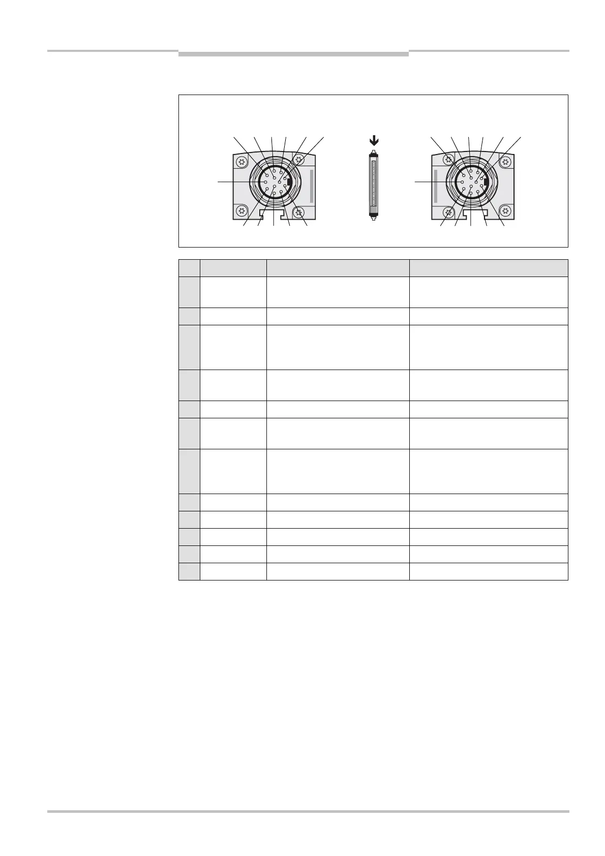
6.3 Extension connection M26)×)11 + FE
Pin Wire colour # Sender " Receiver
1 Brown 24 V DC output (voltage
supply)
24 V DC output (voltage supply)
2 Blue 0 V DC (voltage supply) 0 V DC (voltage supply)
3 Grey Reserved Input emergency stop/bypass/
switch for deactivating the
blanking
4 Pink Reserved Input emergency stop/bypass/
teach-in
5 Red Reserved Reset/restart
6 Yellow Reserved Test output emergency stop/
bypass/teach-in
7 White Reserved Test output emergency stop/
bypass/switch for deactivating the
blanking
8 Red/blue Reserved Output Reset required
9 Black Device communication (EFI
A
) Device communication (EFI
A
)
10 Purple Device communication (EFI
B
) Device communication (EFI
B
)
11 Grey/pink Output host/guest SEL Output host/guest SEL
FE Green Functional earthing Functional earthing
$ The plug alignment (direction of turn) in the housing may vary from device to device. You
can identify the correct pin assignment by the position of the pins in relation to each
other as shown in the drawings.
$ If you do not connect any further safety light curtain to an extension connection, then
you must also not connect any cable to pins 9 and 10.
If the extension connection is no longer required, always screw the attached protective
cap over the extension connection.
Fig. 30: Pin assignment
extension connection
M26
)
×
)
11 + FE
Tab. 16: Pin assignment
extension connection
M26
)
×
)
11 + FE
Notes
8 11 7 6 10 5
1 9234
F
8 11 7 6 10 5
1 9 2 3 4
F