Chapter 4 Operating Instructions
C 4000 Standard/Advanced
26 © SICK AG • Industrial Safety Systems • Germany • All rights reserved 8 009 861/OE59/19-11-04
Configurable functions
Blanked areas require a separate risk analysis!
A blanked area is in principle a hole in the protective field. Check in detail whether and
where blanking is actually required. You must protect the blanked area in another way, e.g.
mechanically. Otherwise you must take the blanked area into consideration in the
calculation of the safety distance and mount the safety light curtain appropriately.
After modifying the blanking, check the protective field with the test rod. Instructions can
be found in chapter 7.3.3 on page 58.
Also pay attention to the warnings in the related chapter.
Properties of blanked areas
$ The C 4000 Advanced is capable of blanking a total of four areas simultaneously.
$ Fixed and floating blanking can be mixed.
$ A minimum of one beam spacing must exist between two blanked areas. The CDS (Con-
figuration & Diagnostic Software) automatically ensures that this is the case during the
configuration. Exception: It is not necessary to maintain any distance between an area of
floating blanking with partial object monitoring and an area of fixed blanking without a
positional tolerance. In this case the effective resolution for the overlapping is equal to
the sum of the effective resolutions in the two areas (see Tab. 10 and Tab. 11).
$ The first beam of the light curtain (close to the 7-segment display) cannot be blanked. It
is needed for the synchronisation between sender and receiver.
$ With fixed blanking, the 7-segment display indicates ? as soon as sender and receiver
are aligned.
%
WARNING
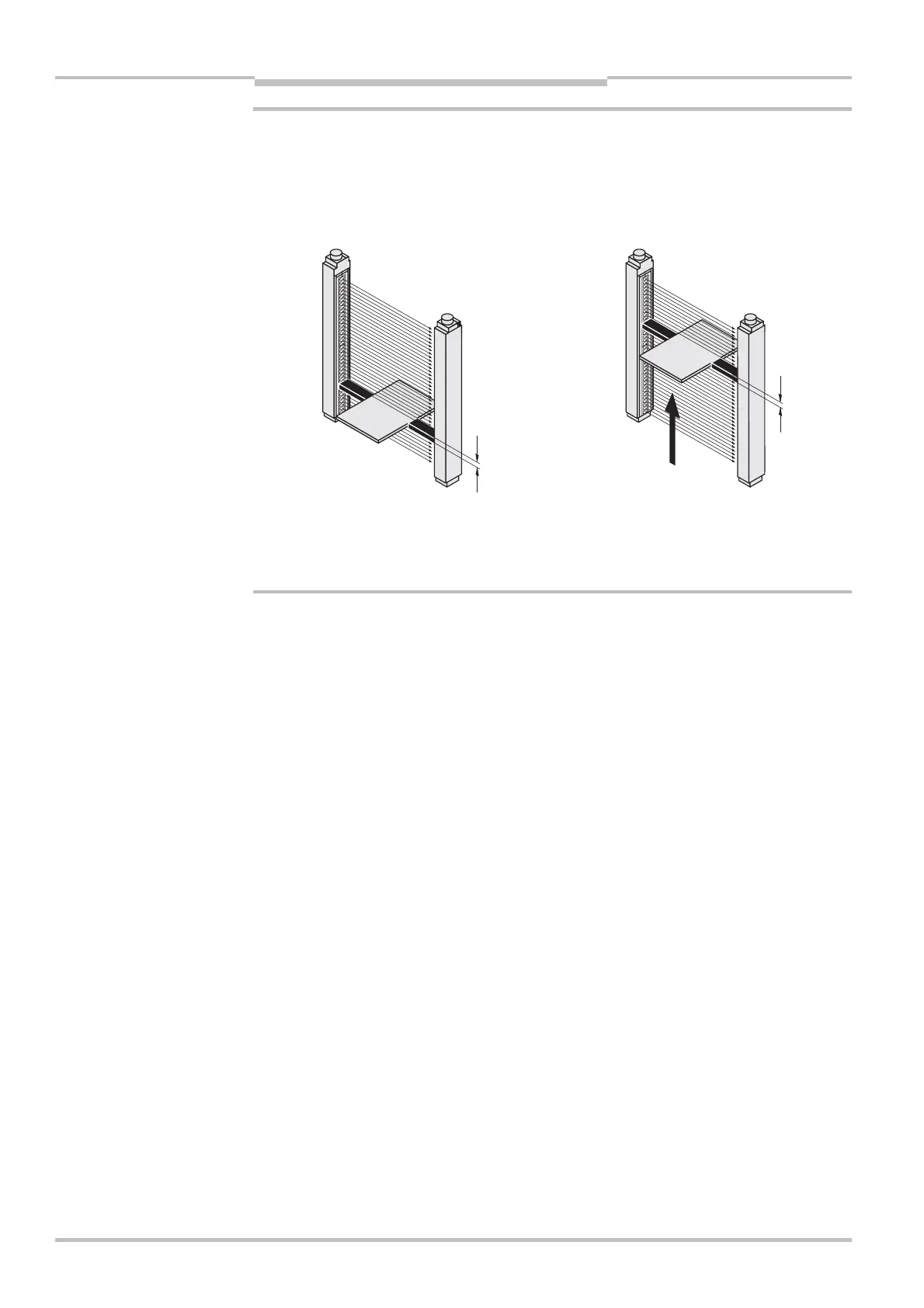
Fig. 10: Example of
mechanical protection of
fixed or floating blanking
Blanked area, sides
protected by
mechanical barriers