14 DUSTHUNTER T · Operating Instructions · 8012428 V 2.0 · © SICK MAIHAK GmbH Germany
Product Description
2.1 Measuring principle, measured variables
2.1.1 Functional principle
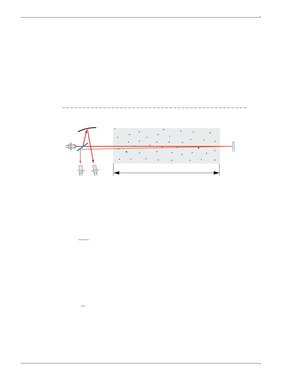
A high performance LED sends light in the visible range (white light, wavelength approx.
450 to 700 nm) through the active measuring path containing particles to the reflector
where it is bounced back to the receiver (
→
Fig. 1). A highly sensitive measurement receiver
accepts the signal weakened by particles, amplifies the signal electrically and feeds it to
the measuring channel of a microprocessor as central part of the measuring, control and
evaluation electronics.
Continuous monitoring of the sender output (partial beam to monitor receiver) registers the
smallest changes in brightness of the light beam sent which then serves to determine the
measurement signal.
Figure 1 Measuring principle
Measured variables
The measuring system uses transmission (T) as primary optical measured variable. The
other measured variables opacity (O), extinction (E) and dust concentration (c) are derived
from this variable.
Transmission, opacity, relative opacity:
Extinction:
LED
Reflector
Measurement Monitor
receiver receiver
Active measuring path
(gas flowing through, free path)
Concave mirror
T = N · N = scaling constant
I
meas
=light received
I
mon
=monitor signal
O = 1 – T
The relative opacity is the opacity related to the stack diameter at the end of the stack.
Transmission and opacity are usually specified in %
I
meas
I
mon
E = log ()
1
T

 Loading...


