Assembly and Installation
DUSTHUNTER T · Operating Instructions · 8012428 V 2.0 · © SICK MAIHAK GmbH Germany 45
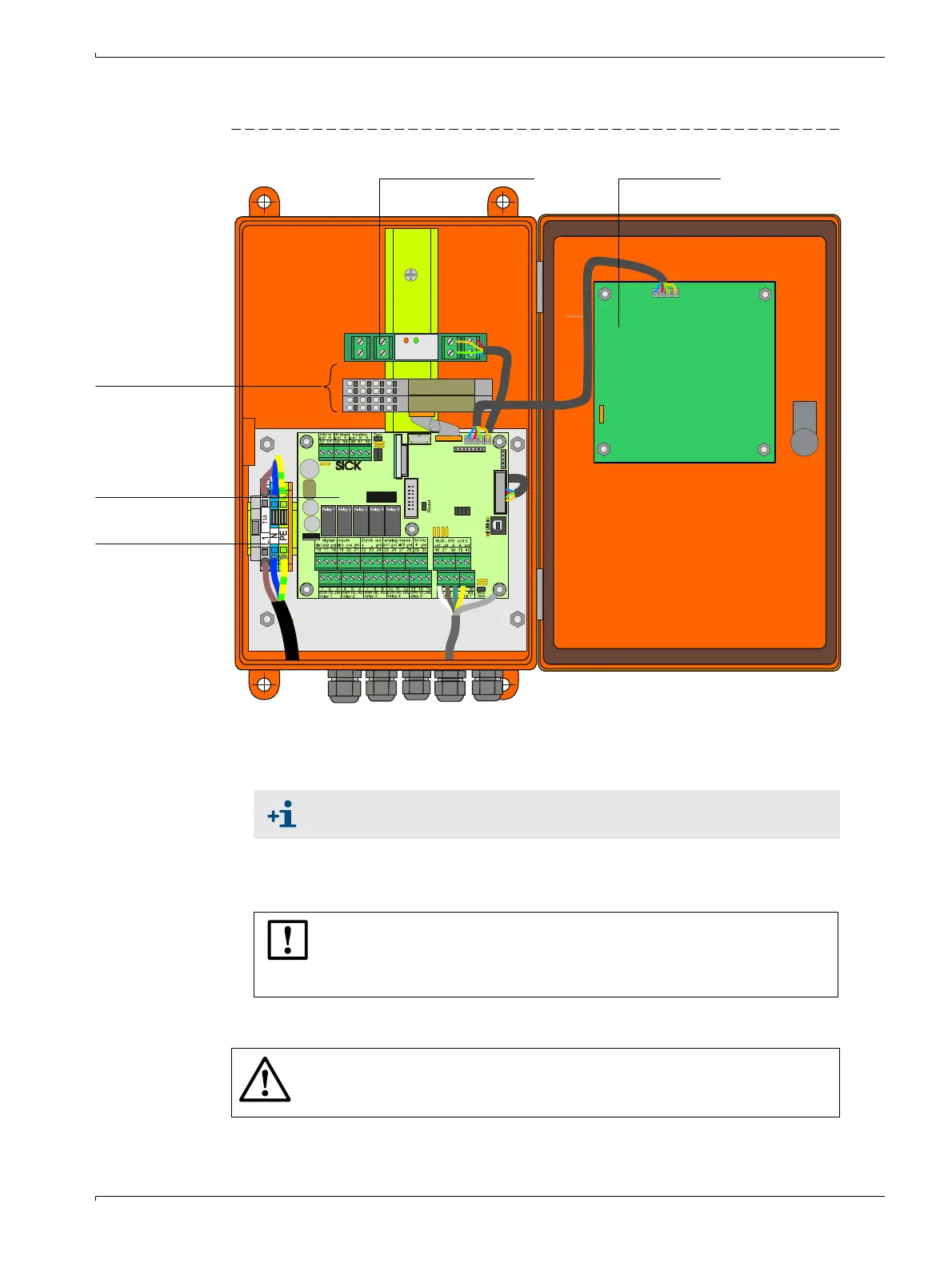
3.3.4 Connecting the MCU control unit
Figure 26 Component layout in the MCU (without purge air supply, with options)
Work to be done
b
Connect connection cable according to
→
p. 47, Fig. 28.
b
Connect cables for status signals (operation/malfunction, limit value, warning, mainte-
nance, check cycle), analog output, analog and digital inputs according to requirements
(
→
p. 47, Fig. 28 and p. 48, Fig. 29 and Fig. 31).
b
Connect power cable to terminals L1, N, PE of the MCU (
→
p. 45, Fig. 26).
Optional I/O modules
Processor board
Terminals for mains
connection
Optional Interface module Display module
If an onsite cable is to be used, it must be connected to a suitable 7-pole
socket
→
p. 48, Fig. 30; SICK Part No.: 7045569).
NOTICE:
b
Only use cables with twisted-pairs and screen (e.g. UNITRONIC LiYCY
(TP) 2 x 2 x 0.5 mm² from LAPPKabel; 1 pair of wires for RS 485, 1 pair
of wires for power supply; not suitable for underground laying).
WARNING:
b
Be sure to check the wiring before switching the supply voltage on.
b
Only modify wiring when disconnected from the mains and potential-free.

 Loading...


