Operating Instructions GM35
Probe Model
Maintenance
8009389/07-2006 © SICK MAIHAK GmbH • Germany · All rights reserved 73
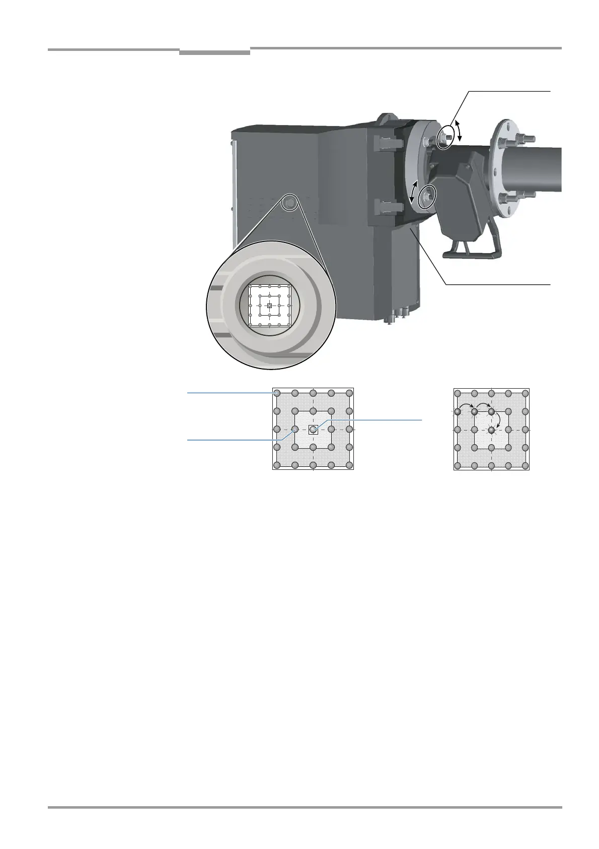
Fig. 39 Aligning the optical axis
Sight The sight indicates the alignment of the optical axis between the SR unit and the reflector in
the probe using a 5 x 5 LED matrix. The LEDs light up to represent the position of the light
beam on the reflector at the end of the probe. The crosshairs show three fields for aligning
the probe.
‡ Adjust the optical alignment as shown in Fig. 39 by altering the two screws on the device
flange using a 19 mm wrench, while monitoring the LEDs at the same time.
A horizontal adjustment of the probe causes the light spot in the sight to shift horizontally;
a vertical adjustment causes it to shift vertically.
The alignment is correct when the lit LED is located within the valid field within the
crosshairs, or is completely within the internal ring marking of the crosshairs.
Note Further notes and meanings of the LED matrix of the GM 35 refer to „Checking on the
Display of the Evaluation Unit“ on page 54
8.4.4 Completing maintenance work at the measuring point
‡ If the SR unit was equipped with a weatherproof cover, remount it.
‡ In the maintenance log, record the work carried out, as well as any special observations,
and notes for future maintenance.
Probe mounting,
horizontal
Probe mounting,
vertical
Outside the
valid field
Optimum
alignment
Valid field

 Loading...


