GM35 Operating Instructions
Probe Model
Commissioning
54 © SICK MAIHAK GmbH • Germany · All rights reserved 8009389/07-2006
Checking on the Display of the Evaluation Unit
Before executing
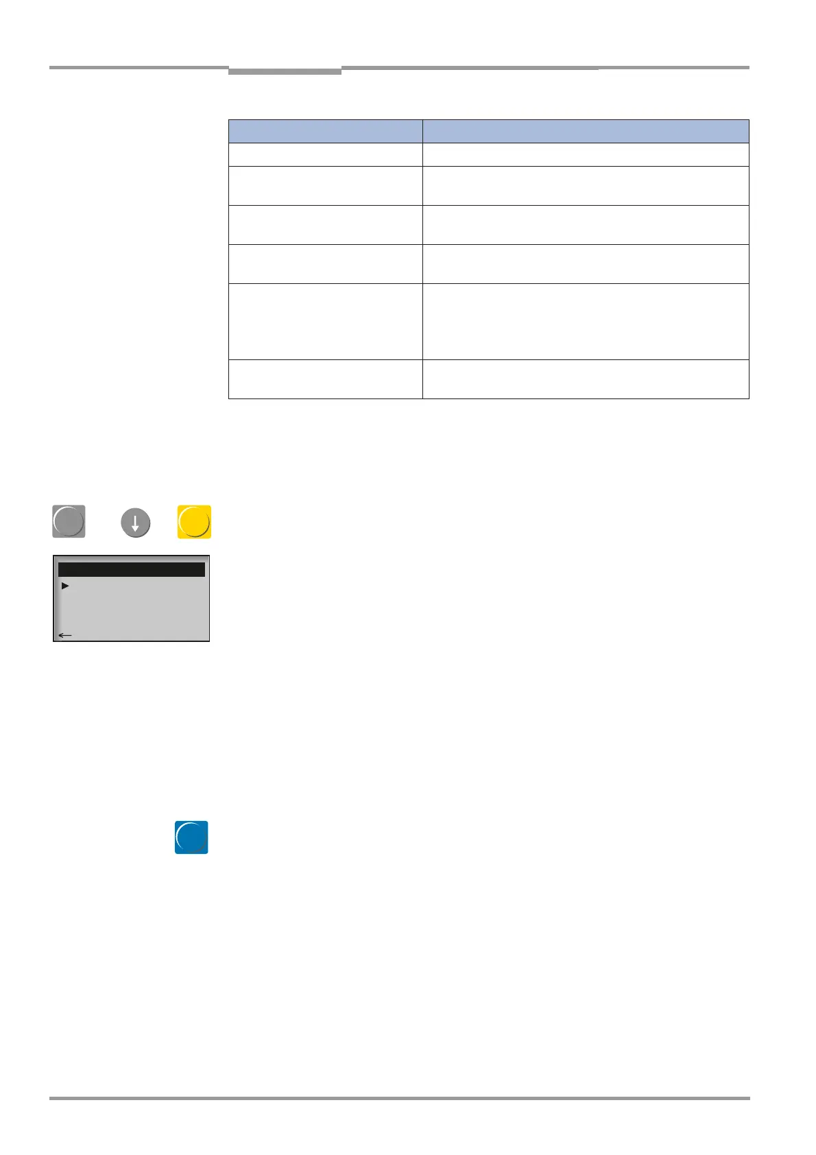
‡ Press diag button, select menu Adjust Probe and call it up with Enter;
with devices with automatic alignment control the optical reference position is started up.
‡ Check the indications on the display:
‡ Adjust the 2 screws at the device flange with 19 mm wrenches (see Fig. 39) until the in-
dications on the display show:
– the values for dx and dy are smaller or equal ±0,1
(dx…value for the horizontal position/adjustment)
(dy…value for the vertical position/adjustment).
The values A, B, C and D are device internal parameters. They should appear in the range
between 450…650.
‡ If the valid area for A to D cannot be attained also after repeated adjusting of the screws,
and are the values for dx and dy ≤ 0.1 check the warning and error messages in the di-
agnosis mode (see „Menu structure“ on page 72) and perform the necessary mainte-
nance and remedy procedures. Refer to chapter „Integrated monitoring and diagnosis
system“ on page 102 and following.
‡ Change to the measuring mode:
‡ Press the meas button.
6.4.4 Zero-point adjustment
After the GM35 SR unit, if necessary the probe and the Evaluation Unit have been connect-
ed to the power supply, a warm-up time of approx. 2.5–5 hours (depending on the ambient
conditions) is required before the zero-point adjustment can be carried out.
‡ If you are using a GPP measuring probe, make sure that the power supply is connected
and that the optical boundary surfaces on the measuring probe are heated.
‡ Wait approx. 2.5 hours after the SR unit has been connected to the power supply. Simi-
larly, if you are using a GPP measuring probe, wait until this warm-up time has elapsed.
Indication in the LED matrix
Meaning
Center LED flashes Analyzer ideal aligned
One LED of the inner square
flashes
Alignment within the half tolerance
One LED of the outer square
flashes
Alignment on the tolerance limits; must to be corrected
One LED of the outer square
blinks
Alignment out of tolerance limits; must be corrected
Center LED blinks No signal; reflector is not "seen" from the SR unit,
because for example the alignment is way out of the
limits, no probe is installed or reflector is strongly con-
taminated.
Lauflicht der mittleren LED-
Reihe
Für die Dauer von Aufwärmphase, Kontrollzyklus, Refe-
renzzyklus ist keine Ausrichtung möglich.
Meaning of the LED matrix of the sight
diag
Enter
A: 467 B: 429
C: 425 D: 438
dx: -0.017
dy: 0.021
Adjust Probe
back save: Enter
meas

 Loading...


