48 DUSTHUNTER T · Operating Instructions · 8012428 V 2.0 · © SICK MAIHAK GmbH Germany
Assembly and Installation
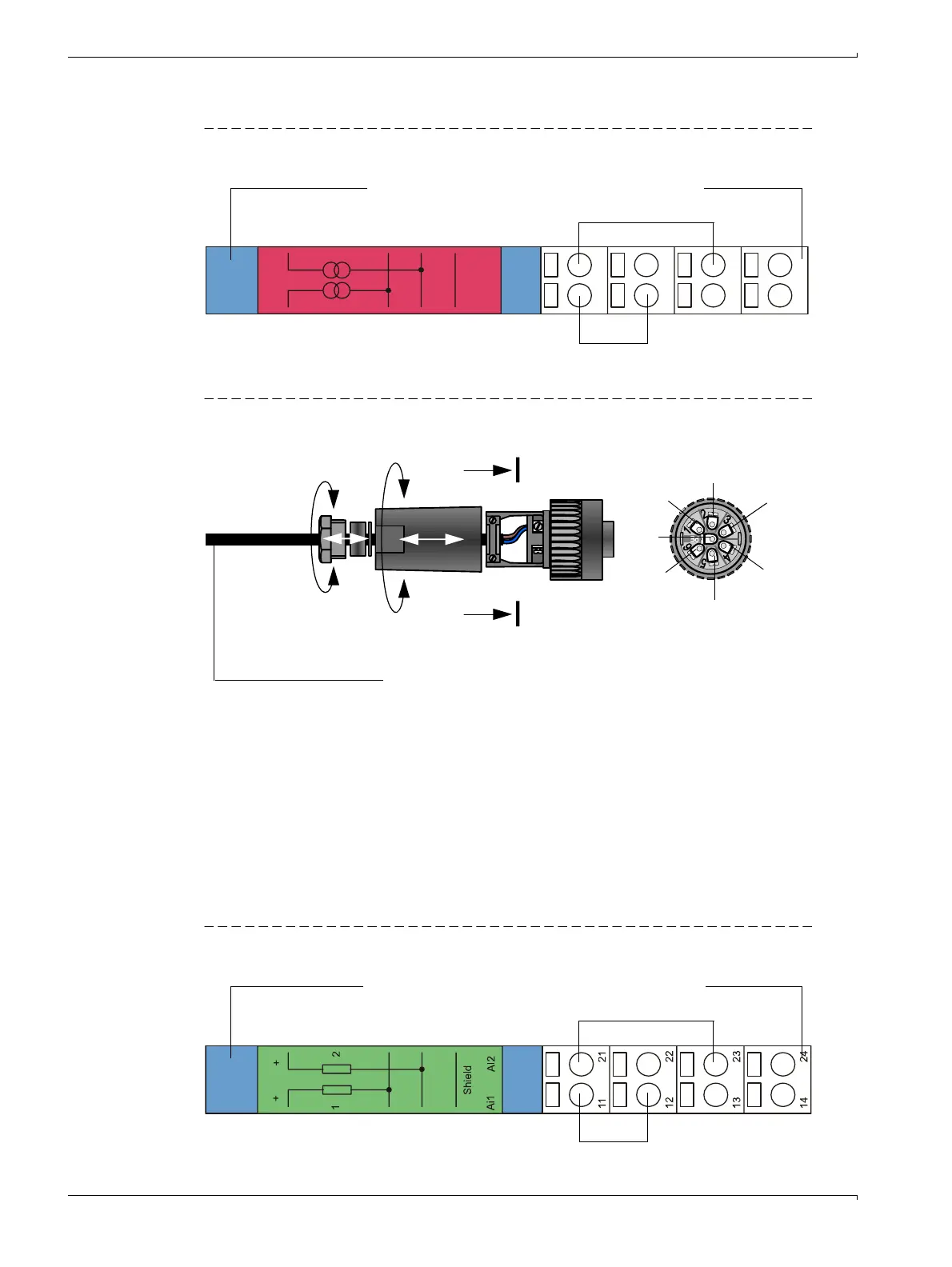
Terminal assignment AO module
Figure 29 Terminal assignment analog output module
Onsite connection cable connection to MCU
Figure 30 Plug-in connector connection on onsite cable
3.3.5
Connecting the reflector on DUSTHUNTER T200
Connect the cable belonging to this component (
→
p. 120, §7.3.2) to the sender/receiver
unit and reflector and screw tight.
3.3.6 Fitting and connecting optional Interface and I/O modules
Plug these modules onto the hat rail in the MCU (
→
p. 45, Fig. 26) and connect to the
associated connection on the processor board with the cable with plug-in connector (
→
p. 46, Fig. 27).
Terminal assignment AI module
Figure 31 Terminal assignment analog input module
+
1
Ao1
+
2
AO2
Shield
11
12
13
14
21
22
23
24
Analog output module Module carrier
AO 2
AO 1
+-
+-
Cable provided by customer
according to page 42, §3.3.1
A
A
A -A
1
+24 V
Note
To open, connect the plug-in connector to the plug
on the sender/receiver unit.
2
3
RS485 B
4
RS485 A
5
6
gnd
7
Screen
Closed
Closed
Open
Open
+-
Analog intput module Module carrier
AI 2
AI 1
+-

 Loading...


