Product Description
DUSTHUNTER T · Operating Instructions · 8012428 V 2.0 · © SICK MAIHAK GmbH Germany 31
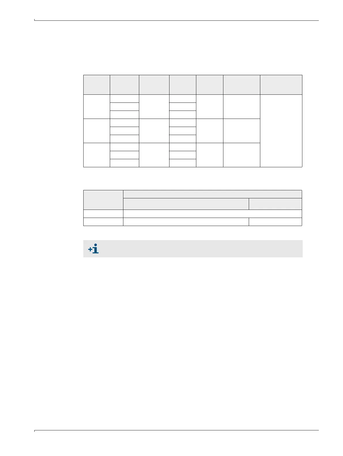
2.3.2 Device configuration
The device components required for a measuring system depend on the respective
application conditions. The following Table should serve to assist you in your selection.
Sender/receiver unit, reflector, flange with tube (standard components)
Voltage and purge air supply
Type DUST-
HUNTER
Active
measuring
path
Sender/
receiver unit
Reflector Cable for
reflector
connection
Type MCU Flange with tube
T50 0.5 ... 2.5 m DHT-T00 DHT-R50 - MCU-
xxON00000N1
Flange with tube
k100
1x each for
sender/receiver
unit and reflector
2 ... 5 m DHT-R51
4 ... 8 m DHT-R51
T100 0.5 ... 2.5 m DHT-T10 DHT-R00 - MCU-
xxON01000NN
2 ... 5 m DHT-R01
4 ... 12 m DHT-R02
T200 0.5 ... 2.5 m DHT-T21 DHT-R10 x MCU-
xxOD01000NN
2 ... 5 m DHT-R11
4 ... 12 m DHT-R12
Internal duct
pressure
hPa
Connection and supply components
Purge air Voltage
-50 ... +2 MCU-P + purge air hose DN 25
-50... +30 Optional external purge air unit + adapter 40-25 MCU-N
We recommend using the optional external purge air unit when the control unit
is > 10 m away from the sender/receiver unit and/or reflector.

 Loading...


