Operating Instructions GM35
Probe Model
Troubleshooting
8009389/07-2006 © SICK MAIHAK GmbH • Germany · All rights reserved 83
9.3.1 Troubleshooting the evaluation unit
9.3.2 Error messages for the GM35 SR unit
The following error messages, which can be displayed on the evaluation unit, refer to the
GM35 SR unit and the purge air attachments.
Error description/message Component/possible cause Remedy
Evaluation unit not respond-
ing
Evaluation unit:
• Power supply to evaluation unit
defective
‡ Check power supply to all system components:
– If necessary, connect on-site power supply
– If necessary, check/reconnect the terminals on the
system components
Evaluation unit:
• Incorrect operating voltage
‡ Check the operating voltage set on the evaluation
unit:
– If necessary, change setting
Evaluation unit:
• Fuse defective
‡ Check the fuse in the evaluation unit:
– If necessary, change fuse
Evaluation unit:
• No defect localized
‡ Disconnect all system components from the power
supply and reconnect them one after the other
– Check the CAN bus cable from the evaluation unit to the
SR unit or terminal box
Evaluation unit:
• Error occurs again
‡ Replace the component last connected; contact the
Service department
Evaluation unit:
• 24V/5V supply defective
‡ Check 24V/5V supply,
Replace evaluation unit or electronic board module;
contact Service department
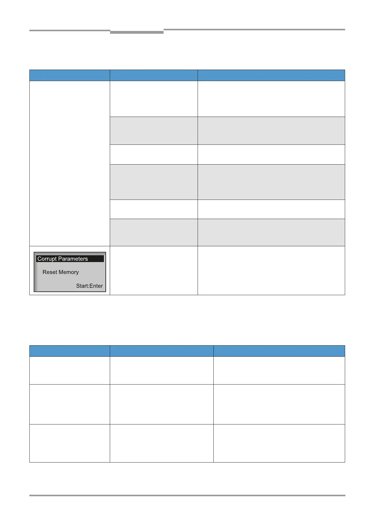
Evaluation unit:
• Inconsistent data detected in
parameter memory
‡ Press Enter to restart the system; the default
parameter settings are then active;
‡ If necessary, reconfigure the parameters
‡ If the same error message occurs again, replace the
evaluation unit and contact the Service department
Error message Component/possible cause Remedy
Air purge low SLV The volumetric flow undershoots the
set threshold.
‡ Check the purge air supply (fan, hoses). If nec-
essary, replace the filter on the purge air fan
(see chapter 8.3.2, page 70.
CO Ampl. max CO instrument amplifier is above the
control range
‡ Check alignment (see page 72).
‡ Clean optical boundary surface (see page 47/
page 68).
‡ Contact the Service department.
CO com. CO
2
/H
2
O module not connected to
CO module
‡ Check whether the cable connection is secure.
Secure/repair it inside the GM35 if necessary.
‡ If fault cannot be corrected: contact Service
department.

 Loading...


