Product Description
DUSTHUNTER T · Operating Instructions · 8012428 V 2.0 · © SICK MAIHAK GmbH Germany 19
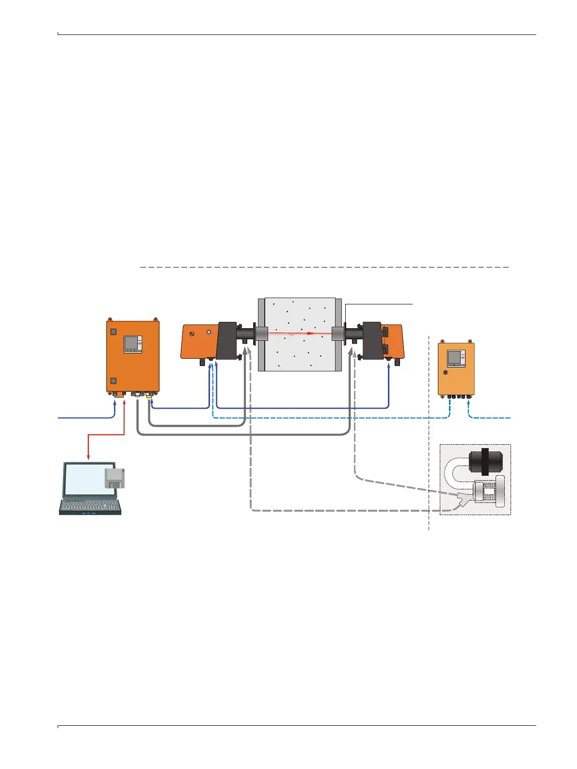
2.2 Device components
Measuring system DUSTHUNTER T comprises the components (
→
Fig. 7):
● Sender/receiver unit DHT-T
● Connection cable to connect the sender/receiver unit to the control unit (lengths 5 m,
10 m)
● Reflector DHT-R
● Connection cable to connect the reflector to the sender/receiver unit (lengths 5 m,
10 m)
● Flange with tube
● Control unit MCU to control, evaluate and output the data of the sender/receiver unit
connected via the RS485 interface
– With integrated purge air supply, for internal duct pressure -50 ... +2 hPa
– Without purge air supply, therefore additionally required:
● Optional external purge air unit, for internal duct pressure -50 ... +30 hPa
● Purge air hose DN25 for supply by control unit MCU-P
Figure 7 DUSTHUNTER T device components
Communication between sender/receiver unit and MCU
As standard, each sender/receiver unit is connected to one control unit via the connection
cable.
Power
Meas
Power
Meas
MCU-P with
purge air
supply
Optional external
purge air unit
Sender/receiver unit
Purge air hose
Connection
cable
Operating and
parameter
setting program
SOPAS ET
Reflector
Flange with tube
Connection cable
USB 1.1
(RS 232)
Power
supply
Duct
Optional
MCU-N
without
purge air
supply
Purge air hose

 Loading...


