44 DUSTHUNTER T · Operating Instructions · 8012428 V 2.0 · © SICK MAIHAK GmbH Germany
Assembly and Installation
3.3.3 Installing the purge air supply
b
Lay the purge air hoses with shortest paths and free of bends, shorten as required.
b
Maintain sufficient distance from hot duct walls.
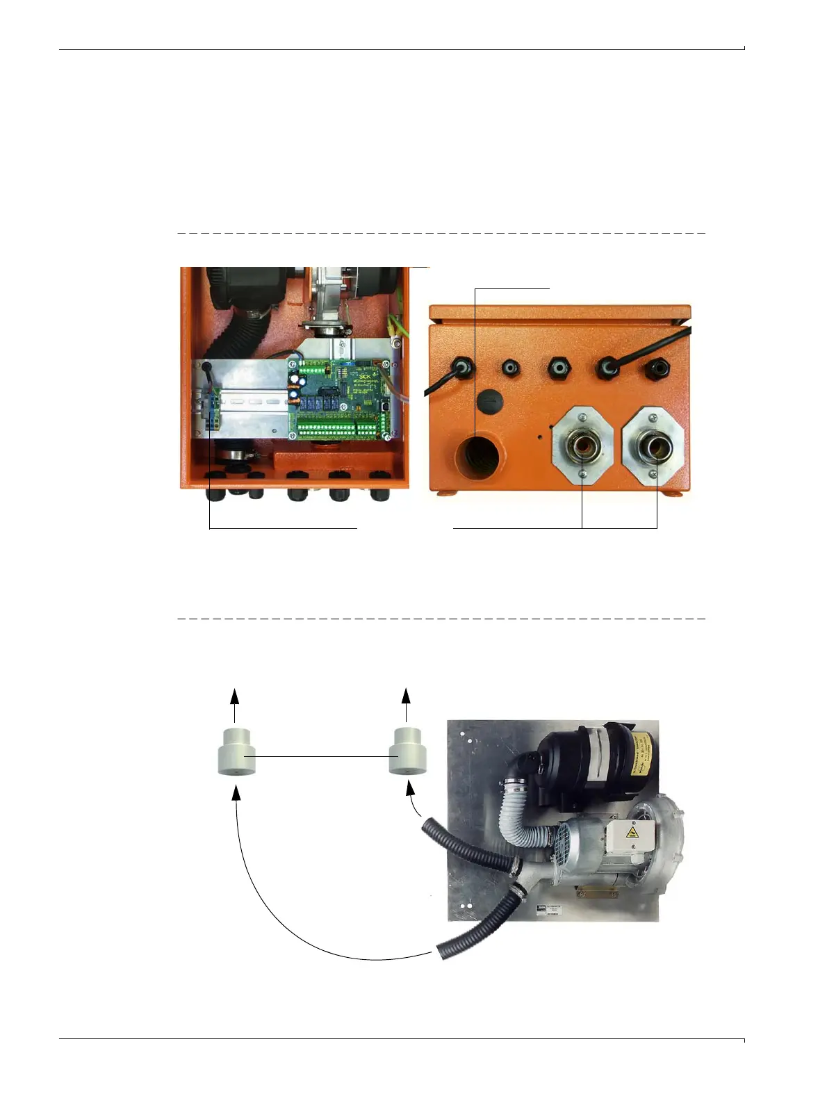
Control unit with integrated purge air supply (MCU-P)
Connect the DN 25 purge air hose to the purge air outlets on the underside of the MCU-P (
→
Fig. 24) and secure with a strap retainer. Set the purge air outlets as shown (correct when
necessary).
Figure 24 Control unit underside with integrated purge air supply
Optional external purge air unit
Connect the DN 40 purge air hose to the Y-distributor of the purge air unit and to the
adapter, and secure with D32-52 hose clamps.
Figure 25 Connecting the optional external purge air unit
Terminals for mains connection DN 25 purge air outlet
Purge air inlet
Optional external purge air unit
Adapter 40-25
To purge air connection of
sender/receiver unit
To purge air connection of
reflector

 Loading...


