40 DUSTHUNTER T · Operating Instructions · 8012428 V 2.0 · © SICK MAIHAK GmbH Germany
Assembly and Installation
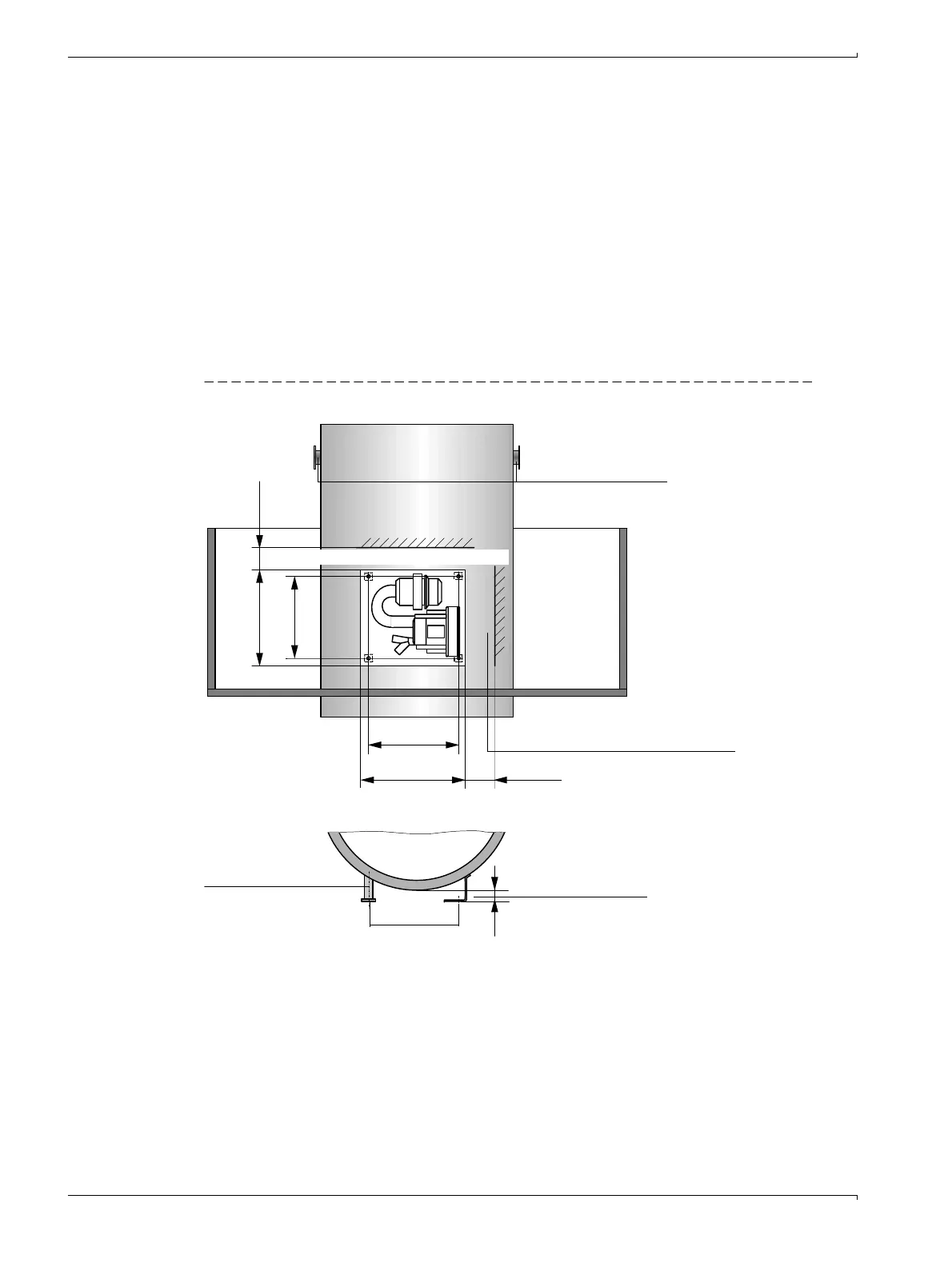
3.2.3 Fitting the optional external purge air unit
Consider the following points when selecting the assembly location:
b
Install the purge air unit at a location with clean air whenever possible. The air intake
temperature must correspond to specifications in the Technical Data (
→
p. 31, §). In
unfavorable conditions, lay an air intake hose or pipe to a location with better condi-
tions.
b
The fitting location must be easily accessible and meet all safety regulations.
b
Install the purge air unit only as far as necessary below the flange with tube for the
sender/receiver unit and reflector so that the purge air hoses can be laid downwards
(avoids water collecting).
b
Provide sufficient clearance to exchange the filter element.
b
Provide sufficient space to attach and remove the weatherproof cover when installing
the purge air unit outdoors
→
Fig. 21).
Figure 21 Purge air unit layout and assembly dimensions (dimensions in mm)
Assembly work
b
Prepare holder (
→
Fig. 21).
b
Fasten purge air unit with 4 M8 screws.
b
Check whether the filter element is fitted in the filter housing otherwise fit when neces-
sary.
> 160
(550)
Duct
Clearance to exchange filter element
> 140
(550)
470
Alternative:
Mounting bracket
Steel pipe 50 x 5
DIN 2391
50
470
M 8
Clearance to fit weatherproof cover
Flange with tube

 Loading...


