Operating Instructions GM35
Probe Model
Commissioning
8009389/07-2006 © SICK MAIHAK GmbH • Germany · All rights reserved 47
6.3.1 Check the delivered components
‡ Check that the SR unit and measuring probe are not damaged.
‡ Make sure that the supply voltage specified on the rating plate of the SR unit matches
the installation conditions.
‡ If a GPP measuring probe is used, also check the supply voltage specified on the rating
plate of the probe.
If necessary, the supply voltage for the GM35 SR unit and measuring probe can be changed
on site by the SICK MAIHAK GmbH service personnel to between 115 V and 230 V.
6.3.2 Protective fittings for transportation
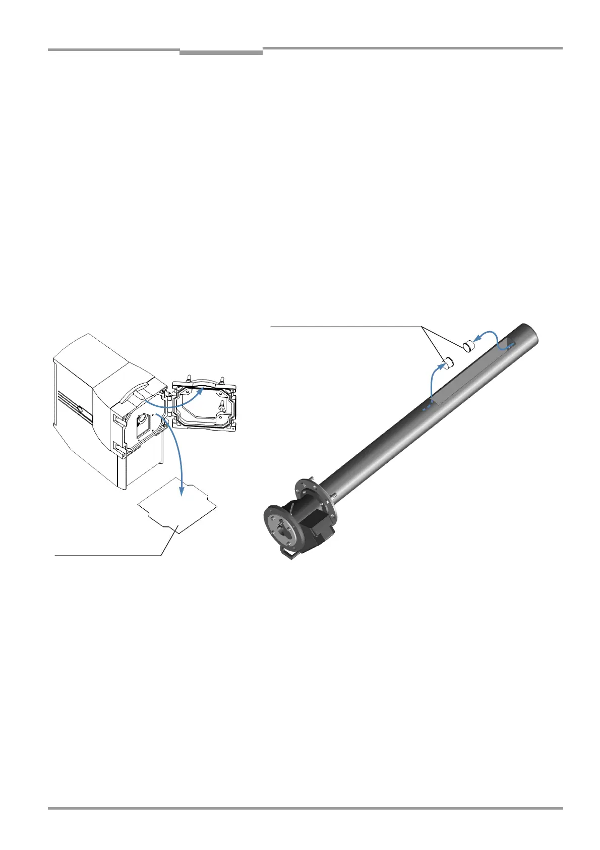
‡ Remove the protective fittings shown below and safety labels (depending on the device
version).
The front cover of the SR unit is clamped between the flange attachment and the housing.
To remove it, open the four quick-release locks and raise the flange attachment (see Fig.).
If necessary, store the protective fittings in a safe place.
Fig. 24 Protective fittings to be removed from the SR unit and measuring probe
6.3.3 Cleaning the optical boundary surfaces
‡ Check the optical boundary surface on the SR unit (front window is shown in Fig. 41 on
page 77) for contamination and clean it if necessary using an optics cloth. Never use de-
tergent, since any residue (even though it may be invisible) will falsify the measurement
result. The cleaning cloths, however, can be moistened using distilled water if necessary.
Suitable cleaning cloths are available as consumables.
Plastic protective caps on the
openings in the aperture on
GMP measuring probes
Front cover of the SR unit
(the shape may be different
from that shown here)

 Loading...


