Operating Instructions GM35
Probe Model
Commissioning
8009389/07-2006 © SICK MAIHAK GmbH • Germany · All rights reserved 53
■ At the EVU display after executing the menu ADJUST PROBE, see page page 52.
If the option "Automatic Aligment Control" is implemented in the GM 35 SR unit, this menu
option in each case must be executed.
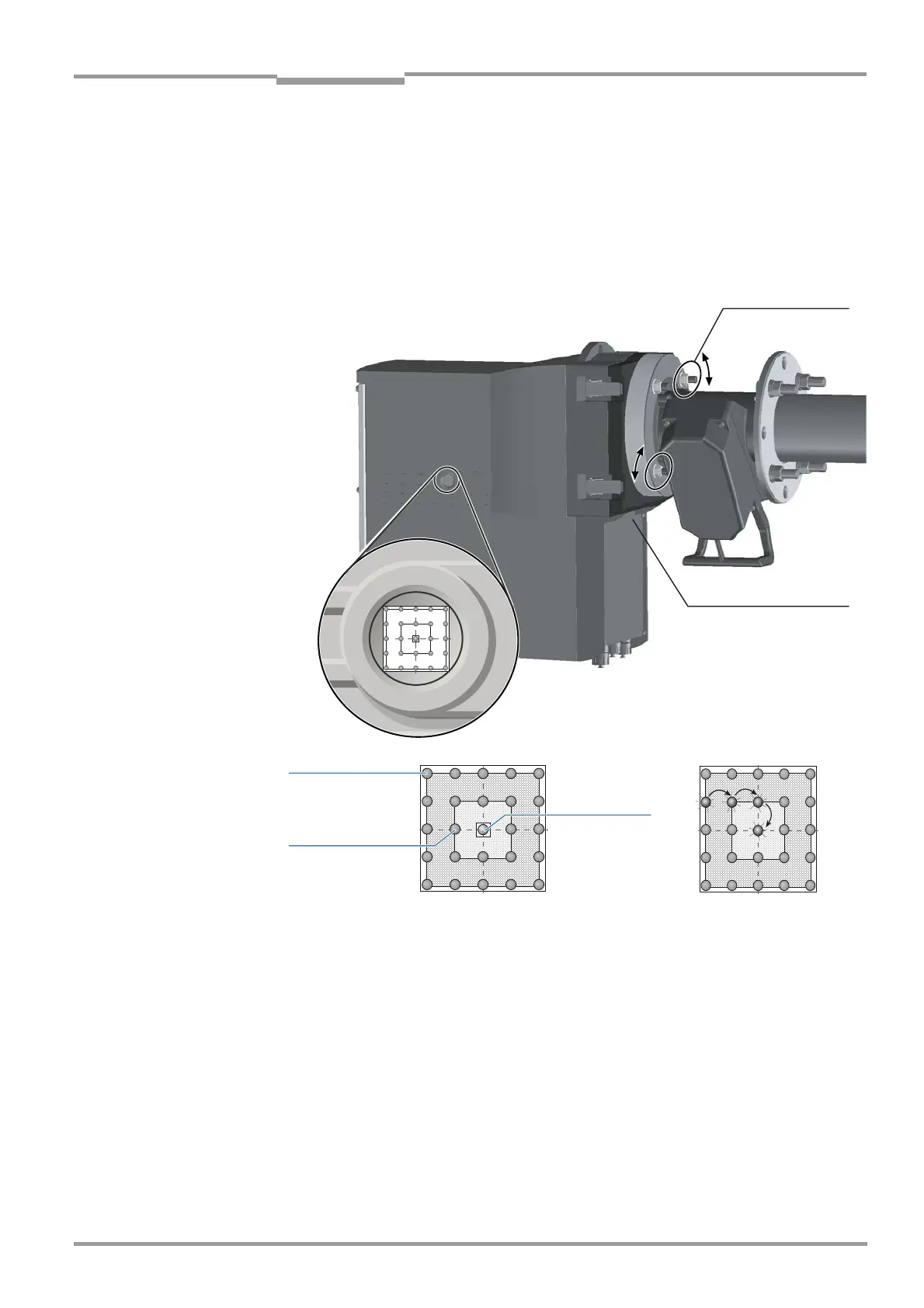
Checking on the visor
The alignment of the optical axis is checked using the sight on the right side of the SR unit
housing and adjusted by varying the probe mounting on the device flange.
Fig. 29 Aligning the optical axis
Sight The sight indicates the alignment of the optical axis between the SR unit and the reflector in
the probe using a 5 x 5 LED matrix. The LEDs light up to represent the position of the light
beam on the reflector at the end of the probe. The crosshairs show three fields for aligning
the probe.
‡ Adjust the optical alignment as shown in Fig. 39 by altering the two screws on the device
flange using a 19 mm wrench, while monitoring the LEDs at the same time.
A horizontal adjustment of the probe causes the light spot in the sight to shift horizontally;
a vertical adjustment causes it to shift vertically.
The alignment is correct when the lit LED is located within the valid field within the
crosshairs, or is completely within the internal ring marking of the crosshairs.
Probe mounting,
horizontal
Probe mounting,
vertical
Outside the
valid field
Optimum
alignment
Valid field

 Loading...


