GM35 Operating Instructions
Probe Model
Commissioning
52 © SICK MAIHAK GmbH • Germany · All rights reserved 8009389/07-2006
Choosing the location ‡ Choose a suitable location to carry out the adjustments using the above information and
the project planning data. Make sure that the requirements listed above are fulfilled at
this location.
6.4.2 Preparations for adjustment
‡ Once the measuring system, consisting of the SR unit and measuring probe, has been
completely assembled, mount it on the bracket to be used for adjustment (e.g. on the
angle flange).
If the system is to be adjusted on the ground, support it securely, ensuring that sufficient
ground clearance is provided for connecting the power supply cable at the bottom of the
device (see Fig. 28), or lay the SR unit on the left-hand side of the housing. The right side
of the unit with the sight must always be accessible.
‡ Connect the 4-pin round connector on the power supply cable provided for the adjust-
ment to the terminal on the bottom of the SR unit. Secure the connector with the knurled
ring.
‡ If you are using a GPP measuring probe, connect the power supply using a cable of the
same type.
‡ Switch on the power supply.
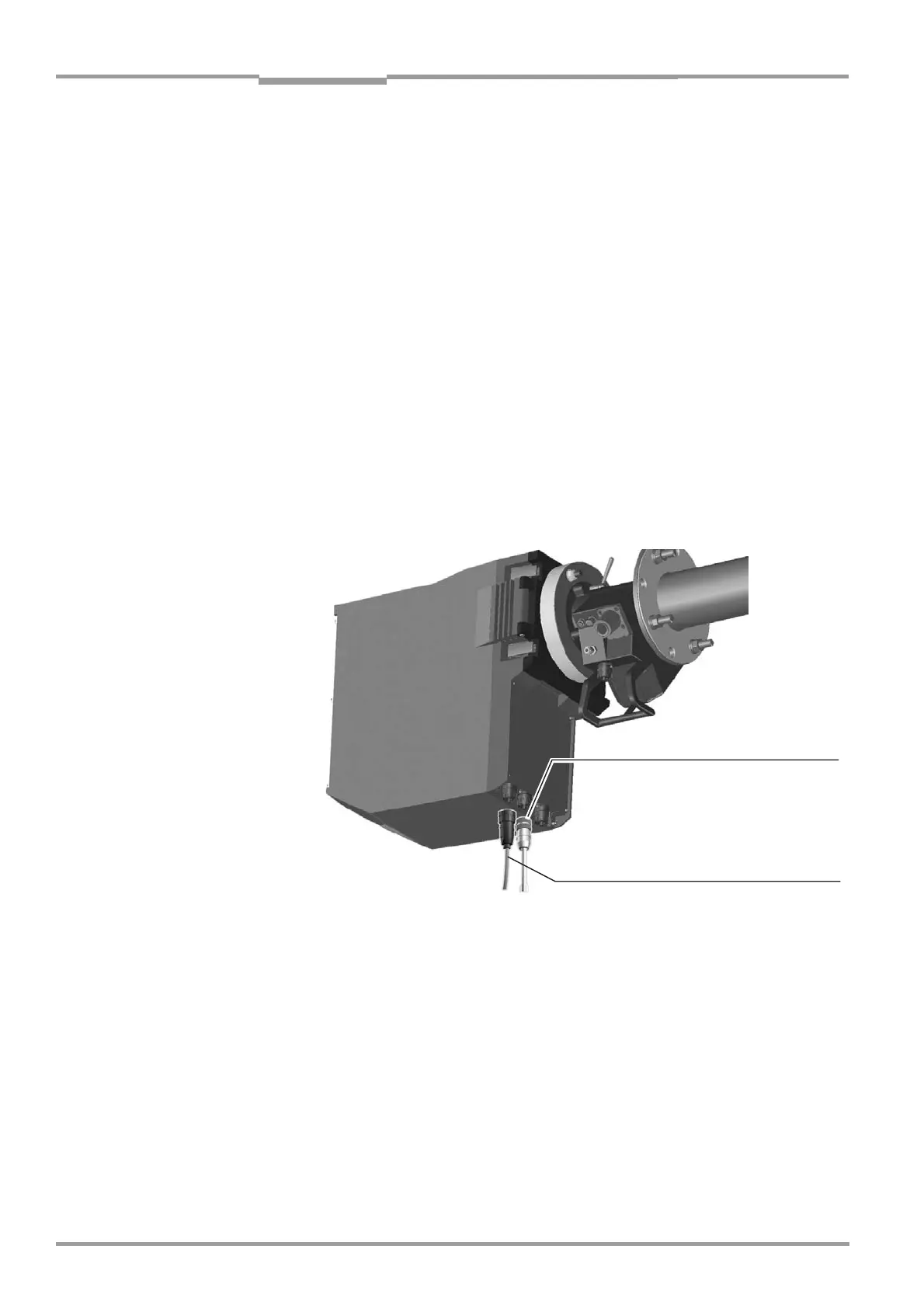
Fig. 28 Connecting the power supply to the SR unit for adjusting the measuring system
6.4.3 Aligning the optical axis
For the guarantee of correct measuring function it is necessary to align the optical axis of
the measuring probe exactly to the light beam of the SR unit. This effected via adjusting 2
screws at the device flange, see Fig. 39 below.
The position of the probe in XY direction can be checked over the
following 2 possibilities:
■ At the visor on the right side of the SR housing, see Fig. 39
Power supply cable with round connector,
art. no. 2 017 519
CAN bus cable to
evaluation unit(if so.
via terminal box)

 Loading...


