Temperature Measurement
Transmitters for rail mounting
SITRANS TR300
two-wire system, universal, HART
3/37
Siemens FI 01 · 2012
■
Overview
"HART" to beat - the universal SITRANS TR300 transmitter
• Two-wire devices for 4 to 20 mA, HART
• Device for rail mounting
• Universal input for virtually any type of temperature sensor
• Configurable over HART
■
Benefits
• Compact design
• Electrically isolated
• Test sockets for multimeters
• Diagnostics LED (green/red)
• Sensor monitoring
open circuits and short-circuits
• Self-monitoring
• Configuration status stored in EEPROM
• Expanded diagnostic functions, such as slave pointer, operat-
ing hours counter, etc.
• Special characteristic
• Electromagnetic compatibility to EN 61326 and NE21
• SIL2 (with order code C20), SIL2/3 (with C23)
■
Application
SITRANS TR300 transmitters can be used in all industrial sec-
tors. Their compact design enables simple mounting on stan-
dard DIN rails on-site in protective boxes or in control cabinets.
The following sensors/signal sources can be connected over
their universal input module:
• Resistance thermometers (2, 3 or 4-wire system)
• Thermocouples
• Resistance-based sensors and DC voltage sources
The output signal is a direct current from 4 to 20 mA in accor-
dance with the sensor characteristic, superimposed by the dig-
ital HART signal.
Transmitters of the "intrinsically safe" type of protection can be in-
stalled within potentially explosive atmospheres. The devices
comply with the Directive 94/9/EC (ATEX).
■
Function
The SITRANS TR300 is configured over HART. This can be done
using a handheld communicator or even more conveniently with
a HART modem and the SIMATIC PDM parameterization soft-
ware. The configuration data are then permanently stored in the
non-volatile memory (EEPROM).
Once the sensors and power supply have been correctly con-
nected, the transmitter outputs a temperature-linear output sig-
nal and the diagnostics LED displays a green light. In the case
of a sensor short-circuit, the LED flashes red, an internal device
fault is indicated by a steady red light.
The test socket can be used to connect an ammeter at any time
for monitoring purposes and plausibility checks. The output cur-
rent can be read without any interruption, or even without open-
ing the current loop.
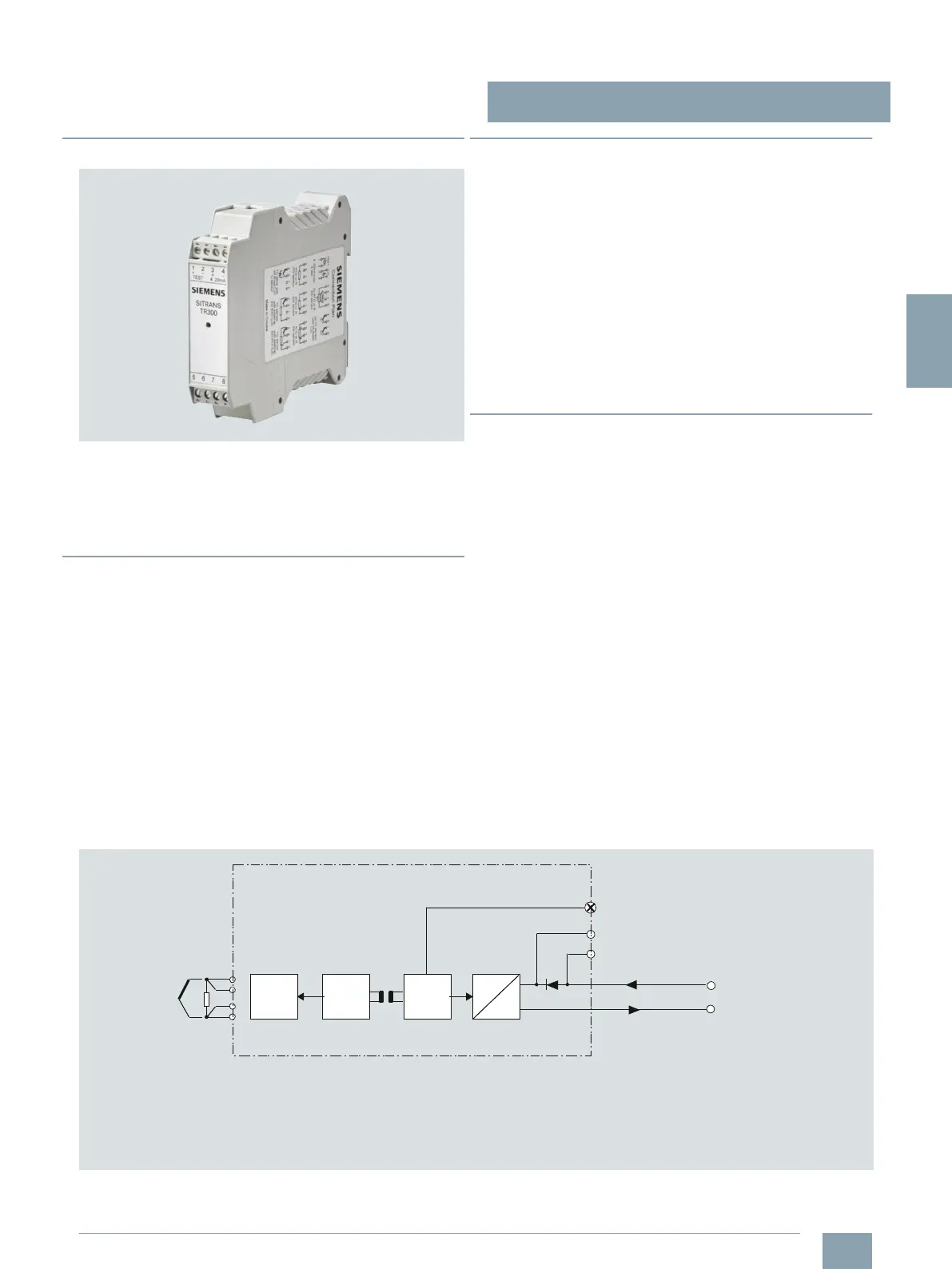
SITRANS TR300 function diagram
1 Sensor such as resistance thermometer,
thermocouple, resistance-based,
sensor, mV sensor
2 Analog-digital converter
3 Microcontroller, secondary circuit
4 Electrical isolation
5 Microcontroller, primary circuit
6 Digital-analog converter
7 LED
U
aux
Auxiliary power supply
I
out
Output current
Test Test terminals for temporary
connection of an amperemeter
Sensor
TC/RTD
A
D
D
A
mC1
mC2
Tes t
4 ... 20 mA U
aux
, I
out
SITRANS TR200/TR300
1
7
6
3
4
5
2
© Siemens AG 2011

 Loading...


