Operating instructions Distance sensors Dx35
Structure and function
16 © SICK AG • Subject to change without notice • 8014868/YEF7/2014-09-02
4 Structure and function
4.1 Structure
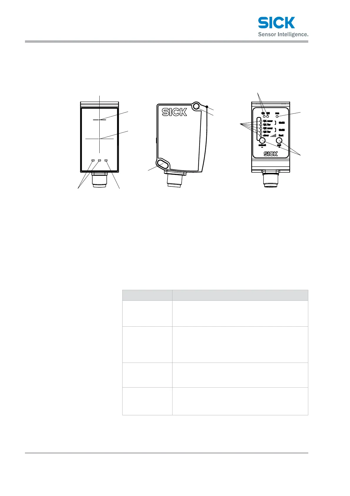
Fig. 4: "Dx35 distance sensor" structure and function
1 Optical axis, sender
2 Optical axis, receiver
3 Zero level
4 Mounting hole M4
5 LEDs, teach-in
6 LEDs, status Q1/Q2
7 LED, status indicator
8 Control elements
LEDs, status Q1/Q2
(continued on next page)
LED Description
Q1 Switching output indicator Q1
• Orange LED: switching output active
• LED off: switching output inactive
Q2 Switching output/Qa analog output indicator Q2
• LED orange: Switching output active/measurement
value within analog output scaling
• LED off: Switching output inactive/measurement value
outside analog output scaling
Q1 and Q2 in run
mode
• "Q1" and "Q2" LEDs ash alternately for longer than
10 seconds: fault exists. Check general conditions
such as supply voltage, temperature range,
EMC disturbances, etc.
Q1 and Q2 in teach
mode
• "Q1" and "Q2" LEDs ash simultaneously: teach is being
performed.
• "Q1" and "Q2" LEDs ash alternately for 5 seconds:
teach failed.