8014868/YEF7/2014-09-02 • © SICK AG • Subject to change without notice 41
Operating instructions Distance sensors Dx35
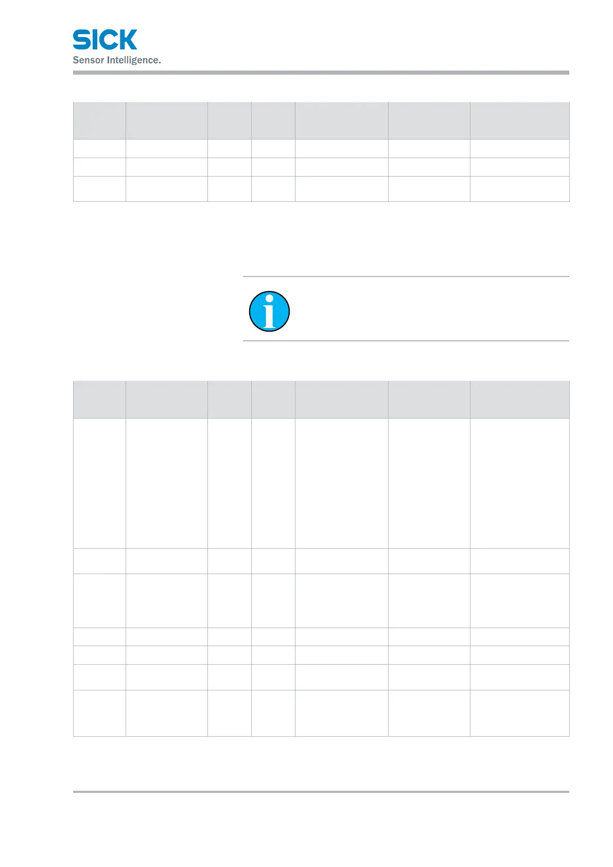
IO-Link interface
Other settings
Index
decimal
(hex)
Description Format Access Value range Example Remarks
84 (0x54) User tag 1 UINT32 R/W 32 bits –
85 (0x55) User tag 2 UINT16 R/W 16 bits –
40 (0x28) Process data UINT16 R 16 bits Content depends on
"process data" setting
Table 14: IO-Link-specic service data – other settings
9.3.2 SICK-specic–outputs
NOTE
In the following tables, the factory settings are indicated
in bold in the "Value range" or "Example" columns.
Index
decimal
(hex)
Description Format Access Value range Example Remarks
69 (0x45) Q1 switching
function
UINT8 R/W • 0: DtO
(Distance to
Object)
• 1: ObSB (Object
between Sensor
and Background)
• 2: Window
• 3: VMA (signal level
warning)
• 4: Alarm (fault
output)
0
70 (0x46) Q1 switching point
near
UINT16 R/W 50 … 50000 mm – In 1 mm steps
72 (0x48) Q1 switching point
far
UINT16 R/W 50 … 50000 mm DT35/DS35:
10000
DL35/DR35:
35000
In 1 mm steps
71 (0x47) Q1 hysteresis near UINT16 R/W 0 … 49550 mm 25 In 1 mm steps
73 (0x49) Q1 hysteresis far UINT16 R/W 0 … 49550 mm 25 In 1 mm steps
94 (0x5E) Q1 near-far center-
ing
UINT16 R/W 50 … 50000 mm – In 1 mm steps
92 (0x5C) Q2 output function UINT8 R/W • 0: 4 … 20 mA
• 1: 0 … 10 V
• 2: Switching
DT35/DL35: 0
DS35/DR35: –