52 FLOWSIC600-XT · Service Manual · 8019179/V0-2/2016-03 · © SICK Engineering GmbH
Repairs
Subject to change without notice
3.5.10 Replacing the cable gland between the Ex-d terminal compartment and the Ex-i
transducer electronics
Prerequisites
▸
The SPU circuit board has been removed:
– Swivel the display unit downwards, → p. 31, §3.5.1.1.
– Remove the electronics cover, → p. 38, §3.5.5.1.
– Remove the SPU circuit board, → p. 39, §3.5.5.2
▸
The Ex-d I/O block has been removed:
– Open the Ex-d terminal compartment, → p. 42, §3.5.6.1.
– Remove the Ex-d I/O block, → p. 42, §3.5.6.2.
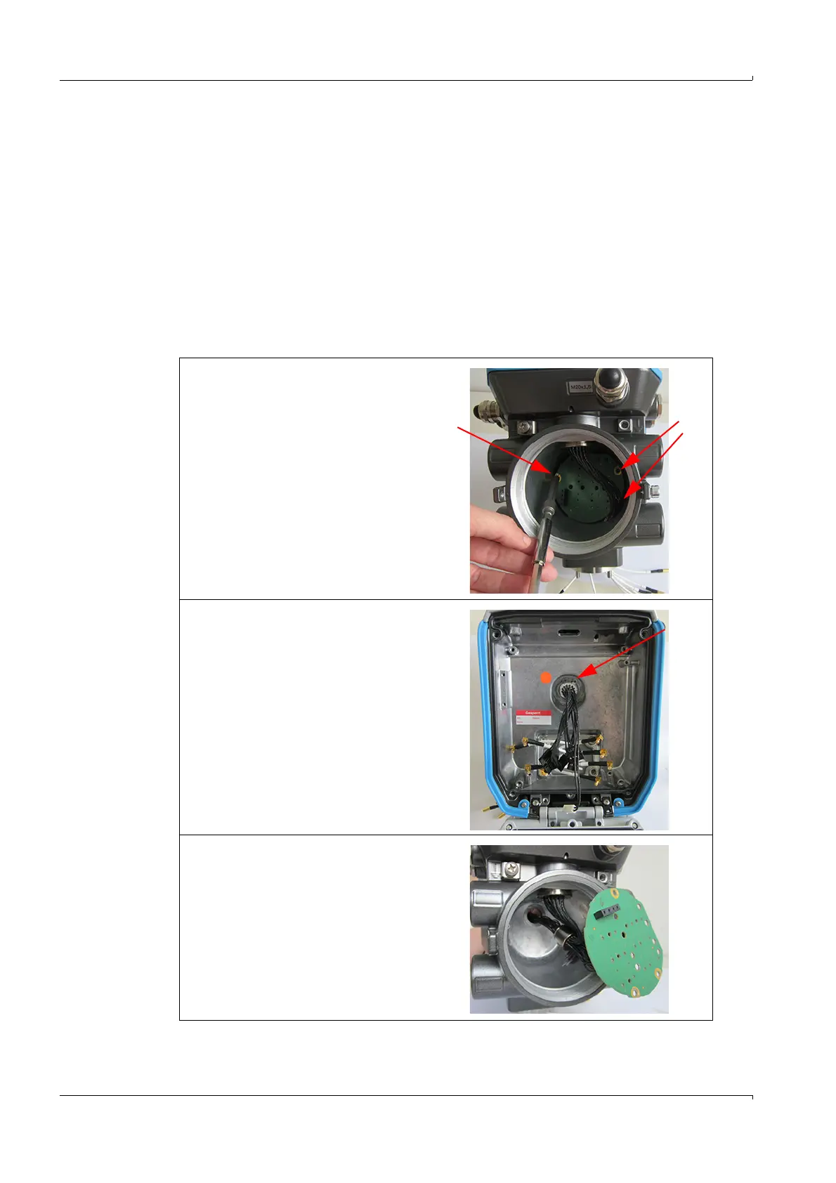
3.5.10.1 Remove the cable gland
1 Loosen the 3 long screws of the
main board.
2 Loosen the snap ring of the cable
gland with the snap ring pliers.
3 Remove the main board with cable
gland.