26 FLOWSIC600-XT · Service Manual · 8019179/V0-2/2016-03 · © SICK Engineering GmbH
Repairs
Subject to change without notice
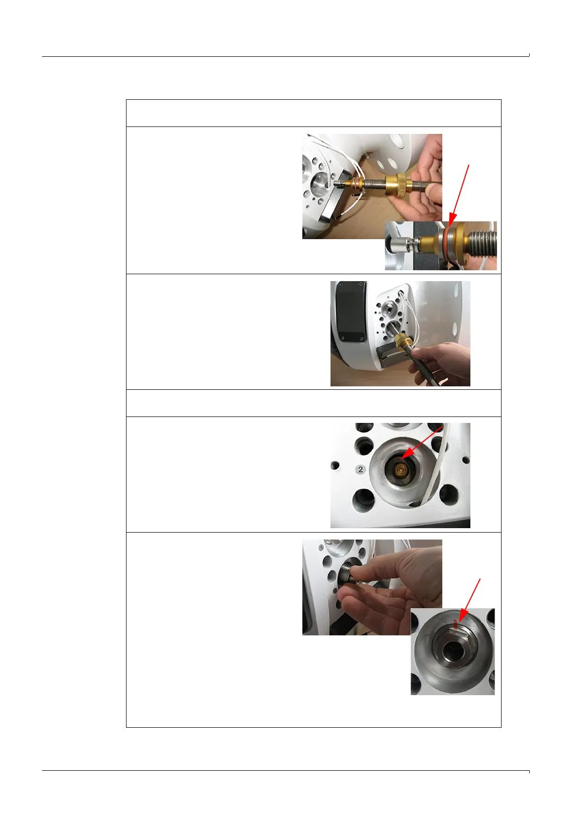
3.4.1.2 Fit the new sensor
1 Unpack the new sensor and check for transport damage. Do not use the sensor when
any damage can be seen at the sensor or the O-ring seal.
2 Screw the new sensor onto the
assembly tool.
3 Grease the O-ring with lubricant.
Important:
– Do not let lubricant into the area
with media contact.
– Step 3 does not apply to oxygen
applications, do not use lubri-
cant!
4 Insert the sensor into the sensor
support until the resistance of the O-
ring seal can be felt.
5 Fix the sensor carefully with one light
axial circular movement.
Important: The O-ring can be easily
damaged. Only position once and do
not tilt!
6 Unscrew the assembly tool from the sensor. If the sensor turns as well, press the
assembly tool slightly from the top and carefully continue to screw.
7 Refit the lock washer.
Make sure the washer does not tilt
otherwise the retaining screw cannot
be completely screwed in.
8 Screw the retaining screw in by hand
9 Then tighten with torque 20 Nm.
Check the position of the manufac-
turer's marking:
– The retaining screw has been
screwed in completely when the
markings are aligned.
– If the markings cannot be
aligned, remove the retaining
screw again and check the lock
washer seating.
10 After sensor replacement, perform a
leak tightness check. Apply leak
detection spray to the sensors and
slowly increase the pressure in the device.