Operation in IO-Link mode: Connect the device to a suitable IO-Link master and inte‐
grate in the master or controller via IODD/function block. The green display LED flashes
on the sensor. IODD and function block are available to download from www.sick.com
under the part number.
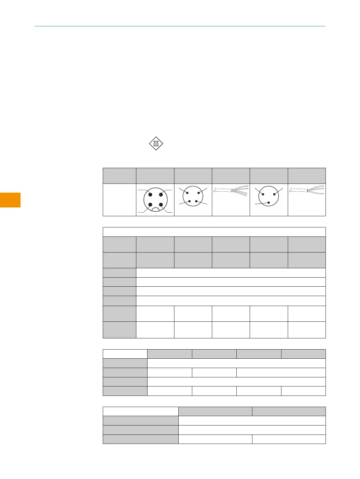
Explanations on connection diagram.
BN = brown
WH = white
BU = blue
BK = black
MF (pin 2 configuration) = external input, teach-in, switching signal
Q
L1
/C = switching output, IO-Link communication
Test = Test input
U
B
: 10 ... 30 V DC
Table 9: Electrical connection
WTB4FT-/
WTB4FA-
x4 x2 xH x1 -xG
1 = BN
2 = WH
3 = BU
4 = BK
0.14 mm
2
AWG26
0.14 mm
2
AWG26
Table 10: DC
WTx4Fx-xxXXXxxxA00
Push-pull 161 162 16A 16N 16xxxxA01-
A99
PNP 861 862 86A 86N 86xxxxA01-
A99
1 = BN + (L+)
2 = WH MF
3 = BU - (M)
4 = BK Q
L1
/ C
De-
fault: MF
Q
Q No function No function www.sick.com
8022709
De-
fault: Q
L1
(C)
Q
Q
Q
Q
www.sick.com
8022709
Table 11: DC
WTx4Fx- xx112xx0Zxx xx111xx0Zxx xx312xx0Zxx xx311xx0Zxx
1 = BN + (L+)
2 = WH
Q
Q No function
3 = BU - (M)
4 = BK Q
Q
Q
Q
Table 12: DC
WTx4Fx- xx311xx0Zxx xx312xx0Zxx
1 = BN + (L+)
3 = BU - (M)
4 = BK Q
Q
5 ELECTRICAL INSTALLATION
22
O P E R A T I N G I N S T R U C T I O N S | WTB4F SingleLine / DoubleLine 8025300.1FCK/2022-02-14 | SICK
Subject to change without notice
en