8
Press-turn element / Potentiome‐
ter / Teach-Button: adjusting the
sensing range
4
3
1
2
16 12,1
8,1
3,5
37,2
4,7
9 8
6
9
Ø 6,8
L
M12
42
5
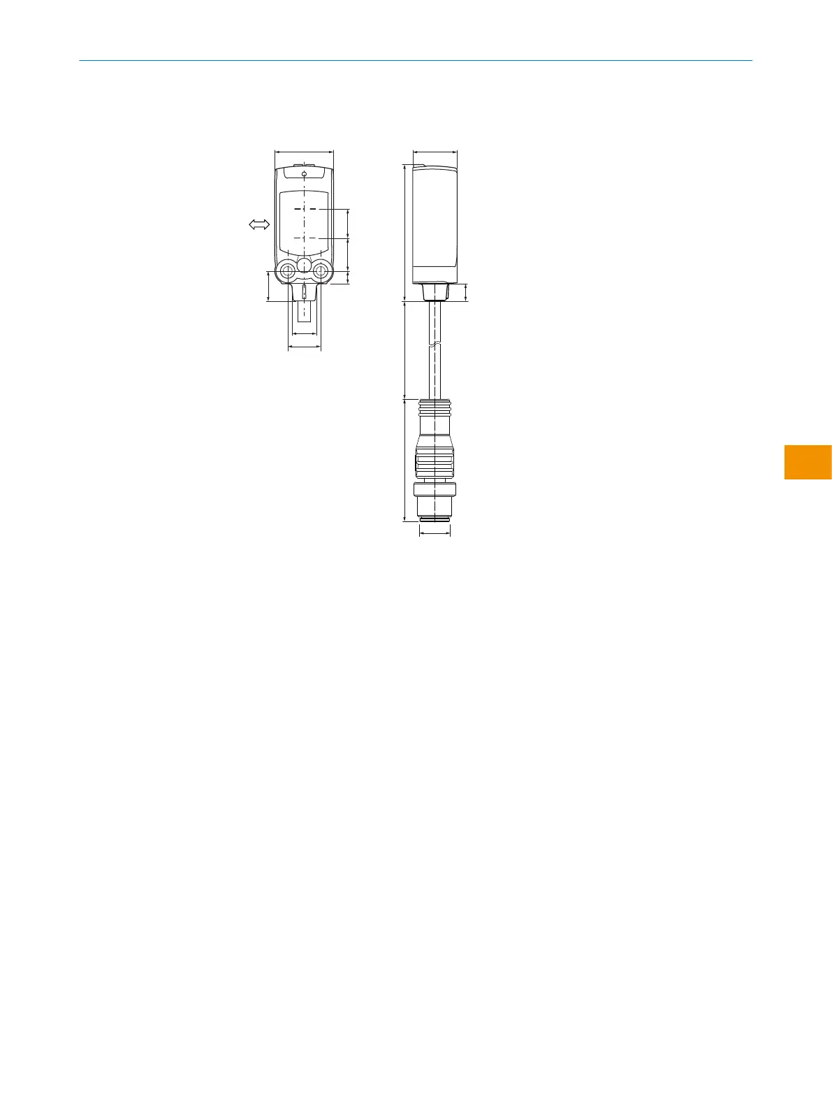
Figure 30: Dimensional drawing 1, cable
with M12 male connector
1
Preferred direction of the target
object
2
Center of optical axis, sender
3
Center of optical axis, receiver
4
M3 threaded mounting hole
5
Cable with M12 male connector
6
Operating and status indicators
L For length of cable, see data sheet
11 Annex
11.1 Conformities and certificates
You can obtain declarations of conformity, certificates, and the current operating
instructions for the product at www.sick.com. To do so, enter the product part number
in the search field (part number: see the entry in the “P/N” or “Ident. no.” field on the
type label).
ANNEX 11
8025300.1FCK/2022-02-14 | SICK O P E R A T I N G I N S T R U C T I O N S | WTB4F SingleLine / DoubleLine
31
Subject to change without notice
en