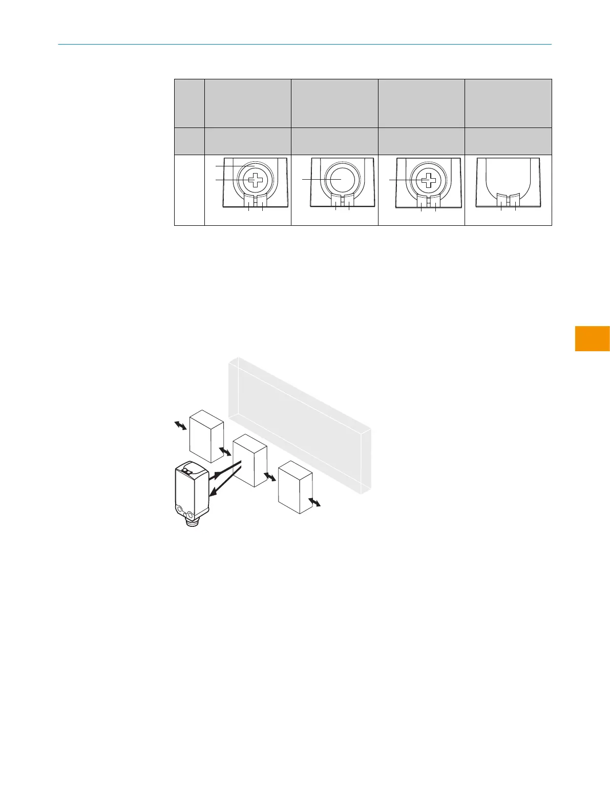
Table 8: Operating elements and status indicators
WTB4
FT-/
WTB4
FA-
xxxxxx20Axx xxxxxx30Zxx xxxxxx10Zxx xxxxxxA0Zxx
Teach-Turn adjust‐
ment
Teach-in button Potentiometer Preset default - no
possibility of setting
1
BluePilot blue: sensing range display
2
Press-turn element / Potentiometer / Teach-Button: adjusting the sensing range
3
Yellow LED: status of received light beam
4
Green LED: supply voltage active
4 Mounting
Mount the sensor using a suitable mounting bracket (see the SICK range of accesso‐
ries).
Figure 16: Alignment of the sensor relative to the object direction
Note the sensor’s maximum permissible tightening torque of < 0.4 Nm.
Note the preferred direction of the object relative to the sensor, cf. see figure 16,
page 21.
5 Electrical installation
Operation in standard I/O mode:
The sensors must be connected in a voltage-free state. The following information must
be observed, depending on the connection type:
– Male connector connection: Pin assignment
– Cable: Wire color
Only apply voltage/switch on the voltage supply once all electrical connections have
been established.
PRODUCT DESCRIPTION 3
8025300.1FCK/2022-02-14 | SICK O P E R A T I N G I N S T R U C T I O N S | WTB4F SingleLine / DoubleLine
21
Subject to change without notice
en