3UG4.1 line monitoring relay
6.2 3UG4511 line monitoring relay
3UG4 / 3RR2 monitoring relays
Manual, 05/2016, NEB927043002000/RS-AC/004
103
3UG4511 line monitoring relay
6.2.1
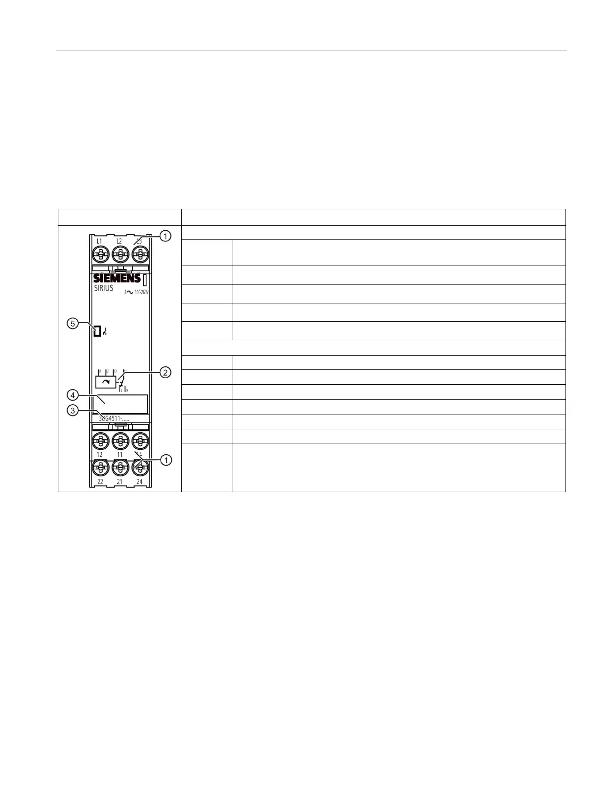
Operator controls and connection terminals
Front view / terminal labeling 3UG4511
Terminal block (removable)
Connection is possible using screw-type terminals or spring-loaded terminals.
Circuit diagram
Device article number
Label
Status display: LED contact symbol (green)
Rated control supply voltage
Output relay K1 CO contact NC contact
Output relay K1 CO contact root
Output relay K1 CO contact NO contact
Output relay K2 CO contact NC contact (on the 3UG4511-.B only)
Output relay K2 CO contact root (on the 3UG4511-.B only)
24 Output relay K2 CO contact NC contact (on the 3UG4511-.B only)
You can find additional information on the connection terminals and the permissible
conductor cross-sections in the Chapter "Connection methods (Page 21)".
You can find information on connecting in the Chapter "Circuit diagrams (Page 106)".