3UG4641 cos phi and active current monitoring relay
11.5 Diagnostics
3UG4 / 3RR2 monitoring relays
Manual, 05/2016, NEB927043002000/RS-AC/004
297
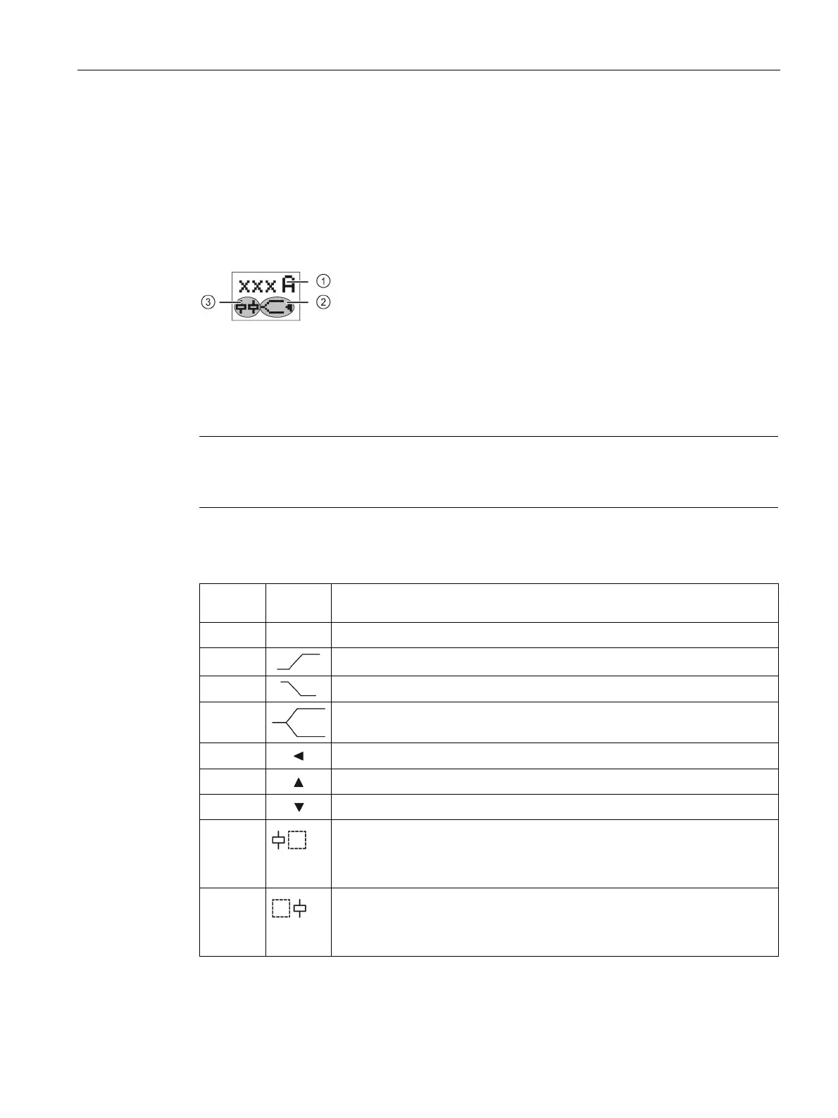
Indications on the display
Display information
The display is divided into three different areas.
Current measuring value / cos phi measuring value or error symbol
Symbols of the changeover contacts
Meaning of the information on the display
Note
Indications in the event of a fault
The symbols on the display flash to indicate an error.
The following statuses and faults are indicated on the display as a diagnostics message with
flashing symbols:
5.0A Displays the measured current
Monitoring for overshoot (φ▲ / I
res
▲) (output relay K2)
Monitoring for undershoot (φ▼ / I
res
▼) (output relay K1)
Window monitoring (φ▲ and φ▼ / I
res
▲ and I
res
▼)
Measuring values are in the correct range
A measuring value overshoot has occurred
A measuring value undershoot has occurred
• Not flashing: Relay contact 11/12 open, relay contact 11/14 closed
• Flashing: Delay time (ON-delay or tripping delay) running
• Masked out: Relay contact 11/12 closed, relay contact 11/14 open
③
• Not flashing: Relay contact 21/22 open, relay contact 21/24 closed
• Flashing: Delay time (ON-delay or tripping delay) running
• Masked out: Relay contact 21/22 closed, relay contact 21/24 open
You will find more information about the switching behavior of the output relay in Chapter
"Functions (Page 291)."



 To Next Page