3UG4621/3UG4622 current monitoring relays
7.6 Circuit diagrams
3UG4 / 3RR2 monitoring relays
182 Manual, 05/2016, NEB927043002000/RS-AC/004
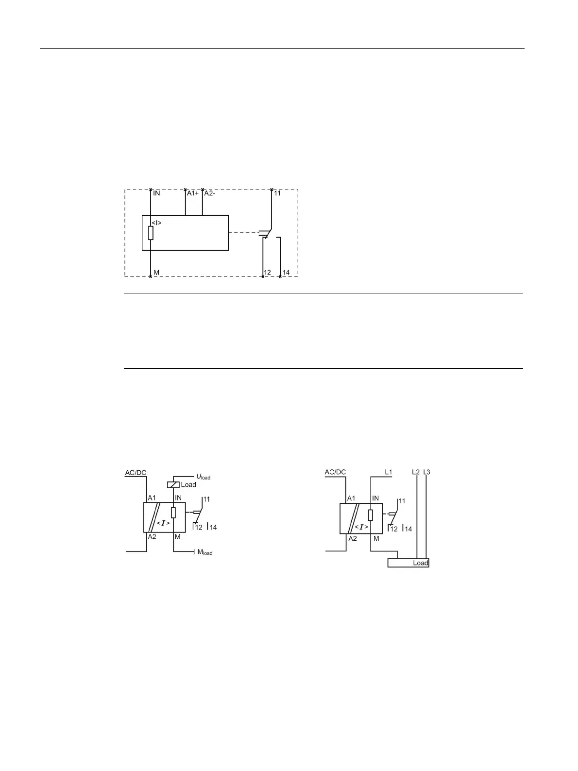
Internal circuit diagrams
Internal circuit diagrams 3UG4621 / 3UG4622 current monitoring relays
V AC / DC version of the 3UG4621/22-.AA30, terminals A2 and M (GND) are
electrically connected in the device! The load current must flow through terminal M (GND).
to 240 V AC/DC versions of the 3UG4621/22-.AW30, terminals A2 and M (GND)
are electrically separated!
Wiring examples (3UG46..-.AW30)
-.AW30 single-phase operation
3UG462.-.AW30 three-phase operation