3UG4651 speed monitoring relay
12.6 Circuit diagrams
3UG4 / 3RR2 monitoring relays
Manual, 05/2016, NEB927043002000/RS-AC/004
315
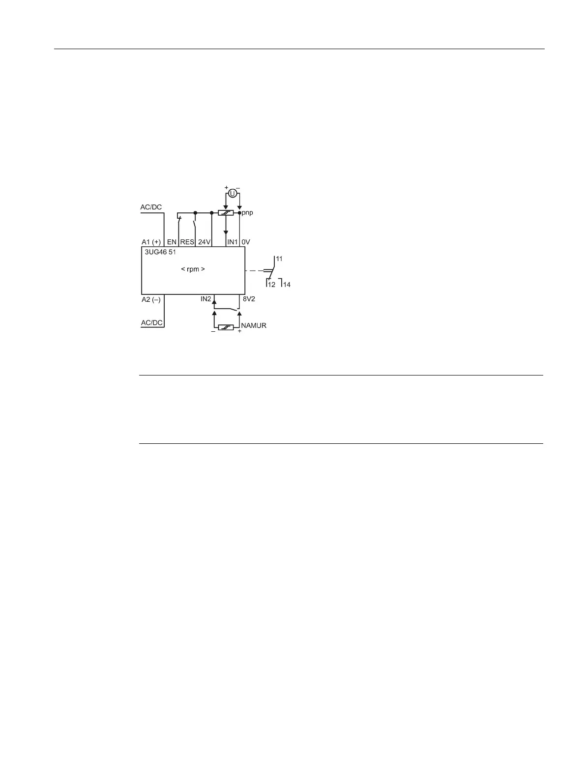
Internal circuit diagrams
Internal circuit diagrams 3UG4651 speed monitoring relay
V AC/DC versions of the 3UG4651-.AA30, terminals A1 / A2 and 0V / 24V are
electrically connected in the device!
to 240 V AC / DC versions of the 3UG4651-.AW30, terminals A1 / A2 and
0V / 24V are electrically separated!