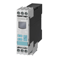
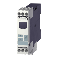
3UG4501 filling level monitoring relay
5.3 Functions
3UG4 / 3RR2 monitoring relays
Manual, 05/2016, NEB927043002000/RS-AC/004
91
Functions
General functionality
The 3UG4501 filling level monitoring relays and the connectable 2-pole or 3-pole 3UG3207-..
probes are used to monitor the filling levels of electrically conductive liquids.
The working principle of the 3UG4501 filling level monitoring relay is based on measurement
of the electrical resistance of the liquid between the probes (minimum and maximum level) or
the reference potential (conductive measurement principle). The output relay changes its
switching state if the measured value is below the sensitivity set on the front. The probes
(e.g. 3UG3207-..) are powered with alternating current (AC measured current) to exclude
electrolysis phenomena in the liquid.
Note
The filling level monitoring relays do not have active monitoring of probe defects or probe
conductor defects. Therefore when selecting the probes
and routing the cable, make sure
that this source of error is precluded. For example, use stable bow probes if wire electrodes
are in danger of being broken.
Depending on their design, the 3UG4501 filling level monitoring relays are powered with a
24 V AC/DC or 24 to 240 V AC/DC rated control supply voltage through terminals A1+ / A2-.
When the rated control supply voltage is applied, the green LED next to the coil symbol on
the device cover lights up.
-.AA30 devices with 24 V AC / DC
versions, as a common reference for the
AC probe voltage at terminals Min and Max, terminal M must not be connected to terminals
A1
/ A2 of the device or grounded!
-.AW30 24 to 240 V AC / DC versions, terminals M, Min, and Max are
ctrically isolated from terminals A1 and A2 of the rated control supply voltage!
Note
The specified voltages represent the absolute thresholds.
Tripping can be delayed by 0.5 to 10 s to avoid tripping the switching function too early when
the level has not quite been reached (e.g. wave motion or foaming of the liquid).
The switching states of the output relay are given below in the section entitled "Function
diagrams."