3UG458. insulation monitoring relay
9.3 3UG4581 insulation monitoring relay
3UG4 / 3RR2 monitoring relays
218 Manual, 05/2016, NEB927043002000/RS-AC/004
3UG4581 insulation monitoring relay
9.3.1
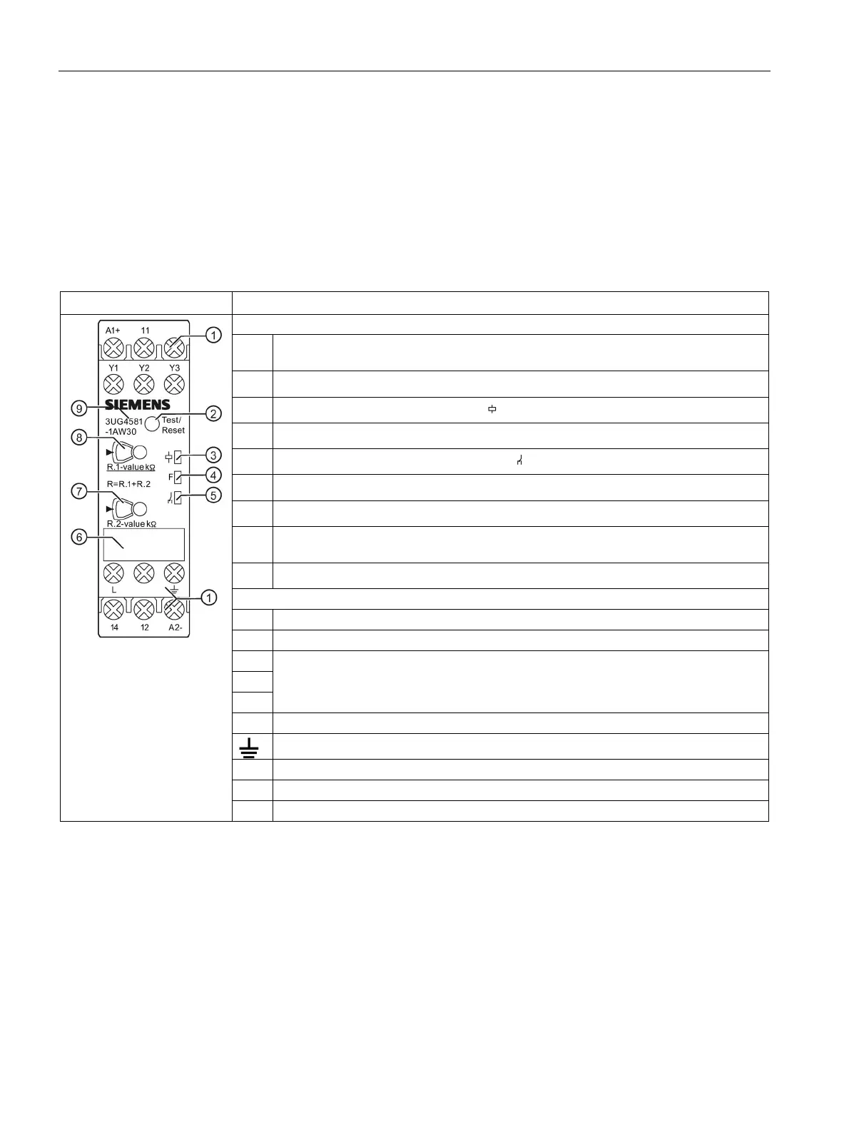
Operator controls and connection terminals
Front view/terminal labeling 3UG4581
Terminal block:
Screw-type connections are possible.
Test/RESET button
1)
Status display: LED for device status
(green)
Status display: LED for monitoring status F (red)
Status display: LED output contact status
(yellow)
Label
Rotary button for adjusting the insulation resistance (R.2 for the units position of R)
Rotary button for adjusting the insulation resistance (R.1 for the tens position of R)
Setting value "0" is colored yellow.
2)
Device article number
Rated control supply voltage ∼ / +
Rated control supply voltage ∼ / -
Control inputs; isolation control
Y1-Y3: Remote test
Y2-Y3: Remote reset/autoreset
Measuring signal input, connection to phase or N conductor
Measuring signal input, ground connection
12 Output relay K1 CO contact NC contact
Output relay K1 CO contact root
Output relay K1 CO contact NO contact
1)
A test is only possible if there is no fault. A reset is only possible if the measured value is
greater than the set threshold including the hysteresis.
2)
Information on setting accuracy
● at setting value "0", a setting accuracy of >15 % applies for R
● at setting value ">1", a setting accuracy of 6 % applies for R
You can find additional information on the connection terminals and the permissible
conductor cross-sections in the Chapter "Technical data (Page 233)".
You can find information on connecting in the Chapter "Circuit diagrams (Page 227)".