Accessories
13.2 Accessories for 3UG4 monitoring relays
3UG4 / 3RR2 monitoring relays
Manual, 05/2016, NEB927043002000/RS-AC/004
343
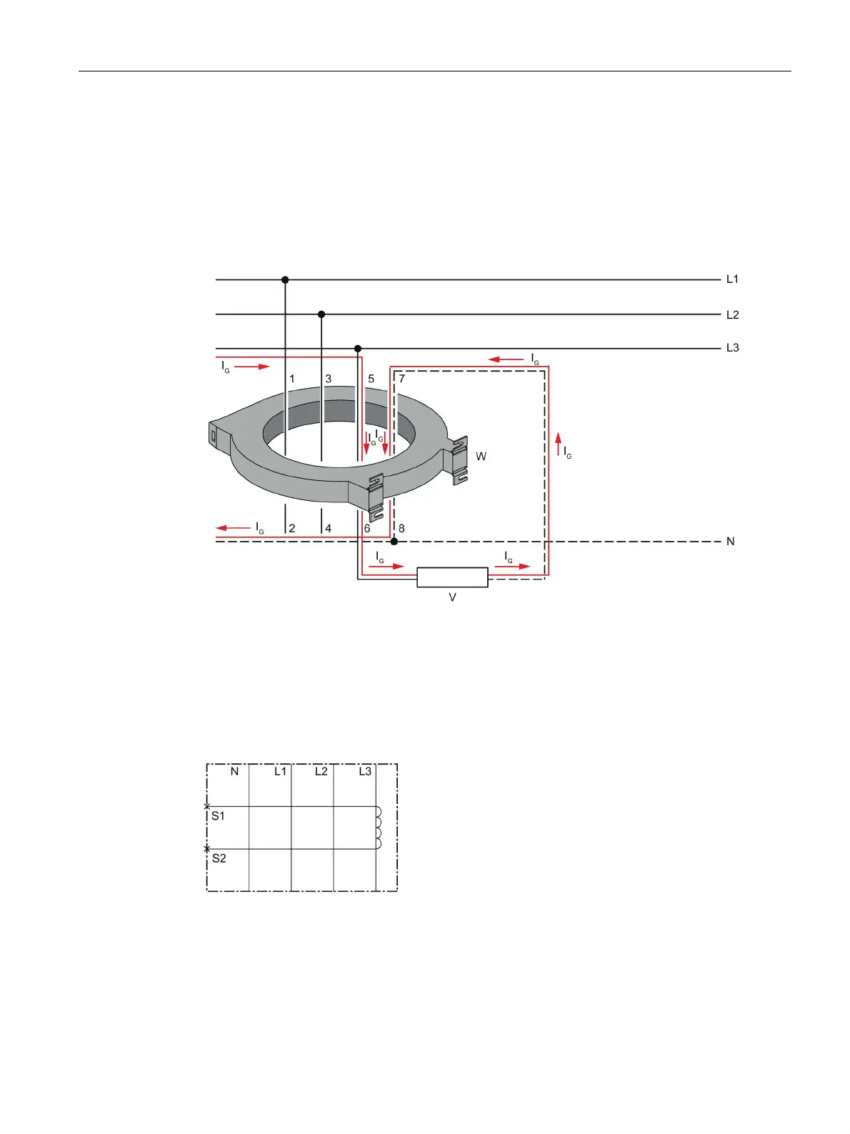
Routing contrary to the current flow
To be able to form the vectorial sum of currents to and from a load correctly, all active
conductors must be routed through the residual current transformer from the same direction.
Due to the restricted space in a control cabinet it may be easier to route the neutral
conductor through the transformer in the opposite direction to the phase conductor. This
means the vectorial sum of currents does not equal zero, even without a ground fault, and
the residual current monitoring relay trips.
Internal circuit diagram
3UL23 internal circuit diagram
Image 13-8 3UL23 residual current transformer