3RR2 current monitoring relays
4.5 3RR22 current monitoring relays
3UG4 / 3RR2 monitoring relays
Manual, 05/2016, NEB927043002000/RS-AC/004
77
Diagnostics
Display information
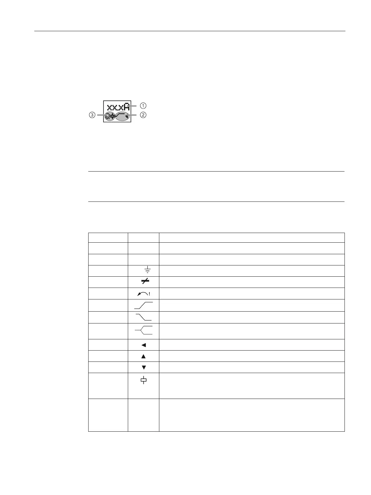
The display is divided into three different areas.
Current measured value or fault symbol
Symbols for the semiconductor contact (left) and the CO contact (right)
Meaning of the information on the display
Note
Indications in the event of a fault
The
symbols on the display flash to indicate an error.
The following statuses and faults are indicated on the display as a diagnostics message with
flashing symbols:
12.5A Displays the measured current
①
n x I▲ Flashing: Current is above the set blocking current
①
I>>
Flashing: Fault current detected
L
Flashing: Cable break/phase failure detected
Flashing: Incorrect phase sequence detected
Monitoring for current overshoot
②
Monitoring for current undershoot
②
Range monitoring (monitoring for current overshoot and current
Current is in correct range
A current overshoot has occurred
A current undershoot has occurred
• Not flashing: Relay contact 31/32 open, relay contact 31/34 closed
• Flashing: Delay time (ON-delay or tripping delay) running
• Masked out: Relay contact 31/32 closed, relay contact 31/34 open
③
Q • Not flashing: Semiconductor output closed, supply voltage connected
• Flashing: Delay time (ON-delay or tripping delay) running
• Masked out: Semiconductor output open, supply voltage not
switched through
You will find more information about the switching behavior of the output relays in Chapter "Function (Page 71)".