3UG458. insulation monitoring relay
9.4 3UG4582/3UG4583 insulation monitoring relays
3UG4 / 3RR2 monitoring relays
236 Manual, 05/2016, NEB927043002000/RS-AC/004
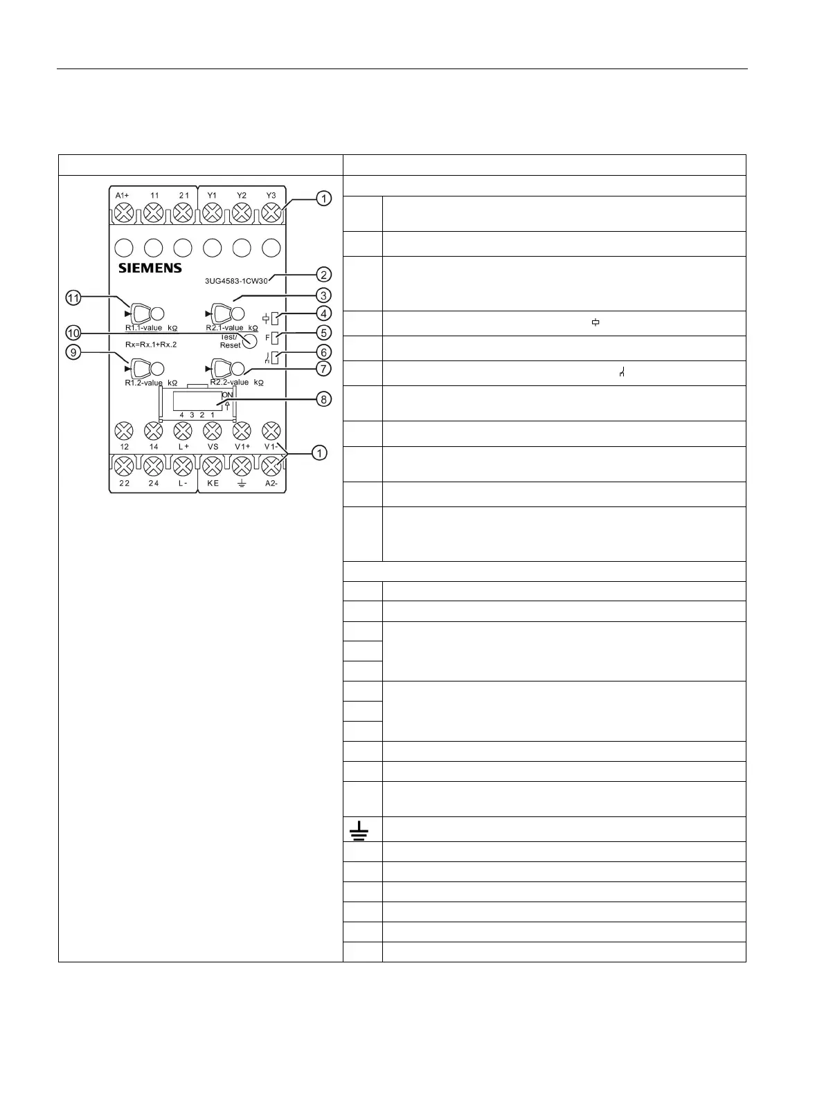
Front view/terminal labeling 3UG4583
Terminal block:
Screw-type connections are possible.
②
Device order number
③
Rotary button for adjusting the insulation resistance (R2.1 for
the tens position of R2)
Setting value "0" is colored yellow.
1)
Status display: LED for device status
(green)
Status display: LED for monitoring status F (red)
Status display: LED output contact status
(yellow)
Rotary button for adjusting the insulation resistance (R2.2 for
the units position of R2)
Label
Rotary button for adjusting the insulation resistance (R1.2 for
the units position of R1)
⑩
Test/RESET button
⑪
Rotary button for adjusting the insulation resistance (R1.1 for
the tens position of R1)
Setting value "0" is colored yellow.
1)
Rated control supply voltage ∼ / +
A2- Rated control supply voltage ∼ / -
Control inputs; isolation control
Y1-Y3: Remote test
Y2-Y3: Remote reset/autoreset
Connection terminals for the upstream module
Measuring signal input, connection to phase or L+
Measuring signal input, connection to phase, N conductor or L-
KE Measuring signal input, control ground connection for open-
Measuring signal input, ground connection
Output relay K1 CO contact NC contact
11 Output relay K1 CO contact root
Output relay K1 CO contact NO contact
22 Output relay K2 CO contact NC contact
Output relay K2 CO contact root
Output relay K2 CO contact NO contact