System overview
3.3 Connection methods
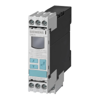
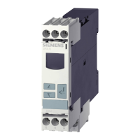
3UG4 / 3RR2 monitoring relays
Manual, 05/2016, NEB927043002000/RS-AC/004
27
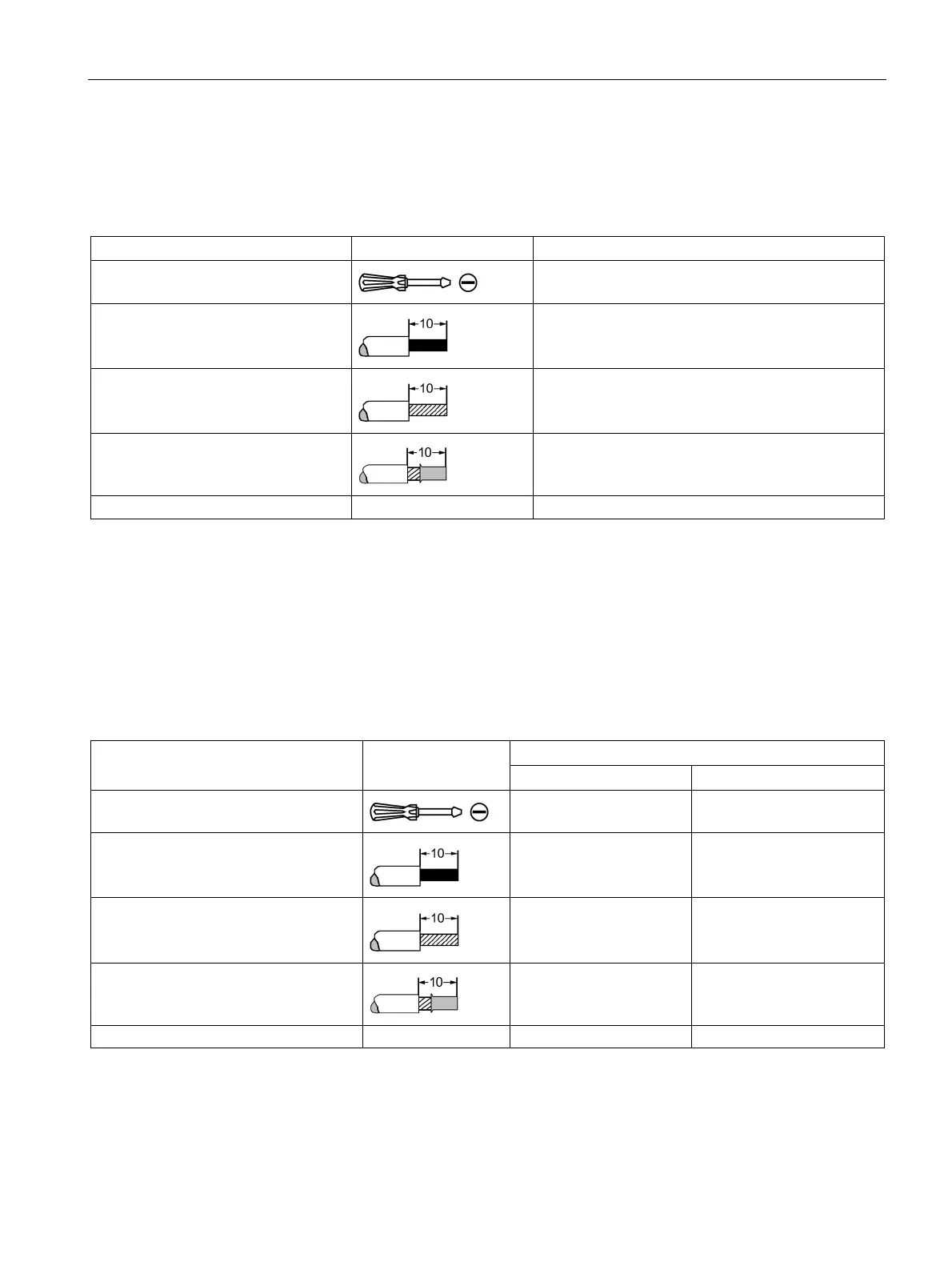
Connection cross-sections of the removable terminal blocks with a spring-loaded connection (3RR
and 3UG)
Table 3- 5 Removable terminal block with spring-loaded connections - monitoring relays
Tool
Ø 3.0 x 0.5 (3RA2908-1A)
Solid and stranded
2 x (0.25 to 1.5) mm²
Finely stranded without end sleeve
2 x (0.25 to 1.5) mm²
Finely stranded with end sleeve
2 x (0.25 to 1.5) mm²
Connection cross-sections of the permanently connected terminal blocks with a spring-loaded
connection
The following table lists the permissible conductor cross-sections for the main conductor
terminals of the 3RR2 current monitoring relays for analog and digital setting (size S00 and
S0) with a spring-loaded connection.
Table 3- 6 Permanently connected terminal block with spring-loaded connection - main conductor terminals of
3RR2 current monitoring relays
Permanently connected terminal
Tool
Ø3.0 x 0.5 (3RA2908-1A) Ø3.0 x 0.5 (3RA2908-1A)
Solid
1 x (0.5 to 4) mm² 1 x (1 to 10) mm²
Finely stranded without end sleeve
1 x (0.5 to 2.5) mm² 1 x (1 to 6) mm²
Finely stranded with end sleeve
1 x (0.5 to 2.5) mm² 1 x (1 to 6) mm²
AWG 1 x (20 to 12) 1 x (18 to 8)