System overview
3.4 Mounting / removal
3UG4 / 3RR2 monitoring relays
Manual, 05/2016, NEB927043002000/RS-AC/004
31
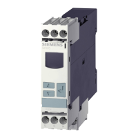
Table 3- 8 Mounting of 3RR2 current monitoring relay, spring-loaded connection system (size S0)
1 Insert the contacts (a) into the central
opening of the spring-loaded
terminals on the contactor (see
below, a), with the contacts flush to
the right. Make sure that the guide
tabs (zoom view) are inserted into the
designated slots on the contactor.
The current monitoring relay will sit
correctly flush with the contactor on
the left- and right-hand sides.
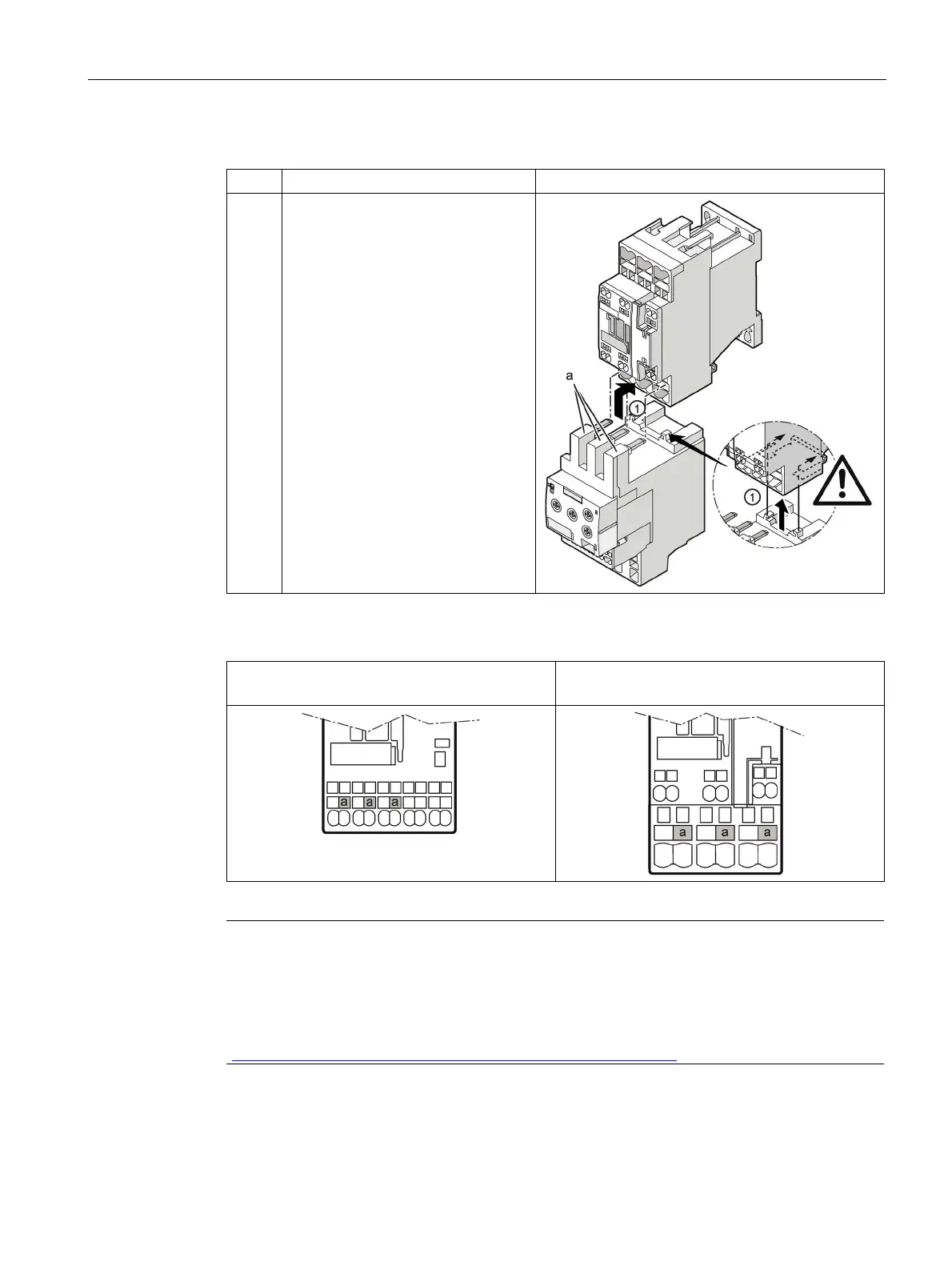
The figures below show the openings of the main conductor terminals on the contactor (S00
and S0) into which the contacts on the current monitoring relay have to be inserted.
Main conductor terminal on the contactor (a)
(S00):
Main conductor terminal on the contactor (a)
(S0):
Note
Adapter for direct mounting on 3RF34 solid-state contactor
For direct mounting on a 3RF34 solid
-state contactor, an additional 3RF3900-
0QA88 adapter
is required, which is attached to the solid
-state contactor. Information is provided in the
"SIRIUS solid state contact
ors / solid state reversing contactors"
http://support.automation.siemens.com/WW/view/en/44362244) operating instructions.