Accessories
13.1 Accessories for 3RR2 current monitoring relays
3UG4 / 3RR2 monitoring relays
Manual, 05/2016, NEB927043002000/RS-AC/004
325
The terminal supports can be snapped onto 35 mm DIN rails according to DIN EN 50022.
They can also be screw-mounted.
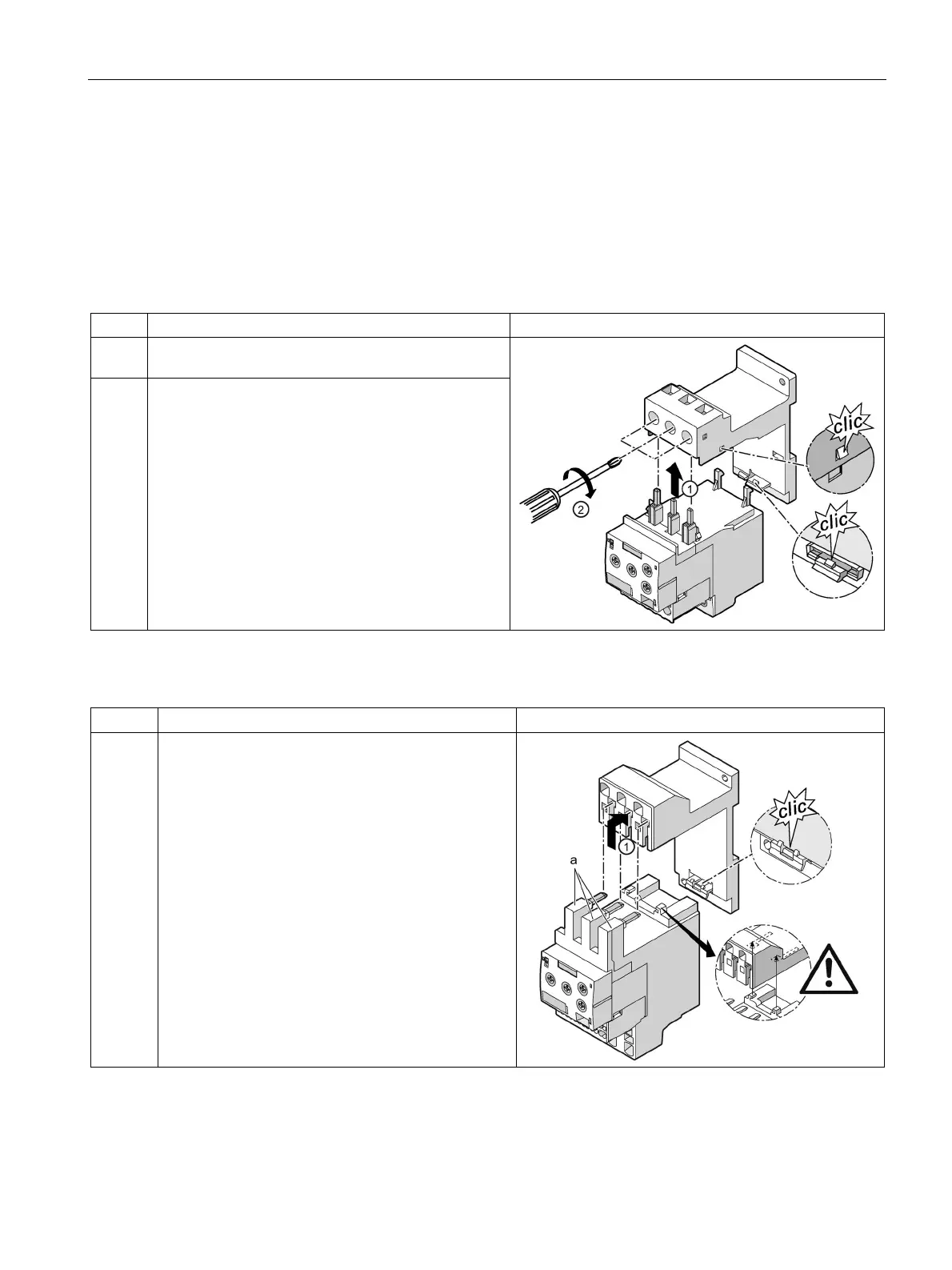
The figure below shows how the terminal support for stand-alone assembly is mounted and
disassembled, based on the example of an analog setting current monitoring relay.
Table 13- 3 Mounting the terminal support (screw connection in the main circuit)
1 Guide the current monitoring relay into the terminal
2 Tighten the screws on the terminal support with a
Pozidriv size 2 (S00) or Pozidriv size 3 (S0)
screwdriver (tightening torque 0.8 to 1.2 Nm).
Check that the cable is clamped tight.
Table 13- 4 Mounting the terminal support (spring-loaded connection in the main circuit)
1 Insert the contacts (a) into the central opening of the
main terminals on the terminal support, with the
contacts flush to the right. Make sure that the guide
tabs are inserted into the designated slots on the
terminal support.