UMSITRPDS3-1 On-Line Operation
November 2005
6-27
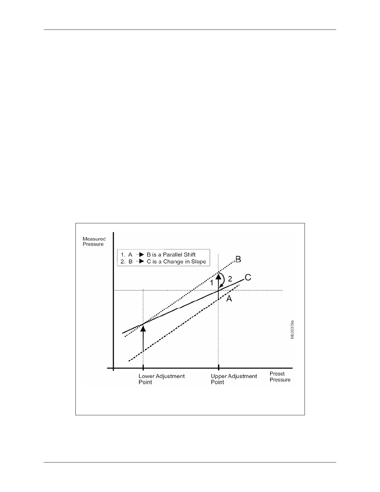
6.4.13.2 Trimming the Upper Sensor Adjustment Point
A pressure representing the upper sensor pressure is applied and the transmitter is instructed to accept this
press. This corrects the characteristic slope; see Figure 6-4. Adjusting the upper sensor adjusting point
will not affect the lower sensor adjusting point. The upper point must be greater than the lower point.
1. Apply a reference pressure representing the lower sensor adjustment point.
2. In the Online menu, press 3 Device Setup.
3. In the Device Setup menu, press 2 Diagnostics/Service.
4. In the Diagnostics/Service menu, press 4 Trim.
5. In the Trim menu press, 2 Sensor Trim.
6. In the Sensor Trim menu, press 4 Upper Sensor Trim. A warning message will appear: “Loop should
be removed from automatic control.” Take the appropriate action and press OK to continue. A second
warning will appear: “This will affect sensor calibration.” Again, press OK to continue.
7. The “Apply hi pressure” message will appear. Press OK to continue. A “Pressure OK when pressure
is stable” message will appear. Press OK to continue.
8. The applied value is displayed next. The value can be changed from the Communicator’s keyboard.
Press ENTER to store the value or press ABORT to exit the procedure without storing a value.
9. Remove the reference pressure.
A
B
C
Output characteristic
Characteristic after lower sensor adjustment
Characteristic after upper sensor adjustment
FIGURE 6-4 Sensor Trim
 Loading...


