Introduction UMSITRPDS3-1
November 2005
1-4
1
2
3
4
5
6
7
8
9
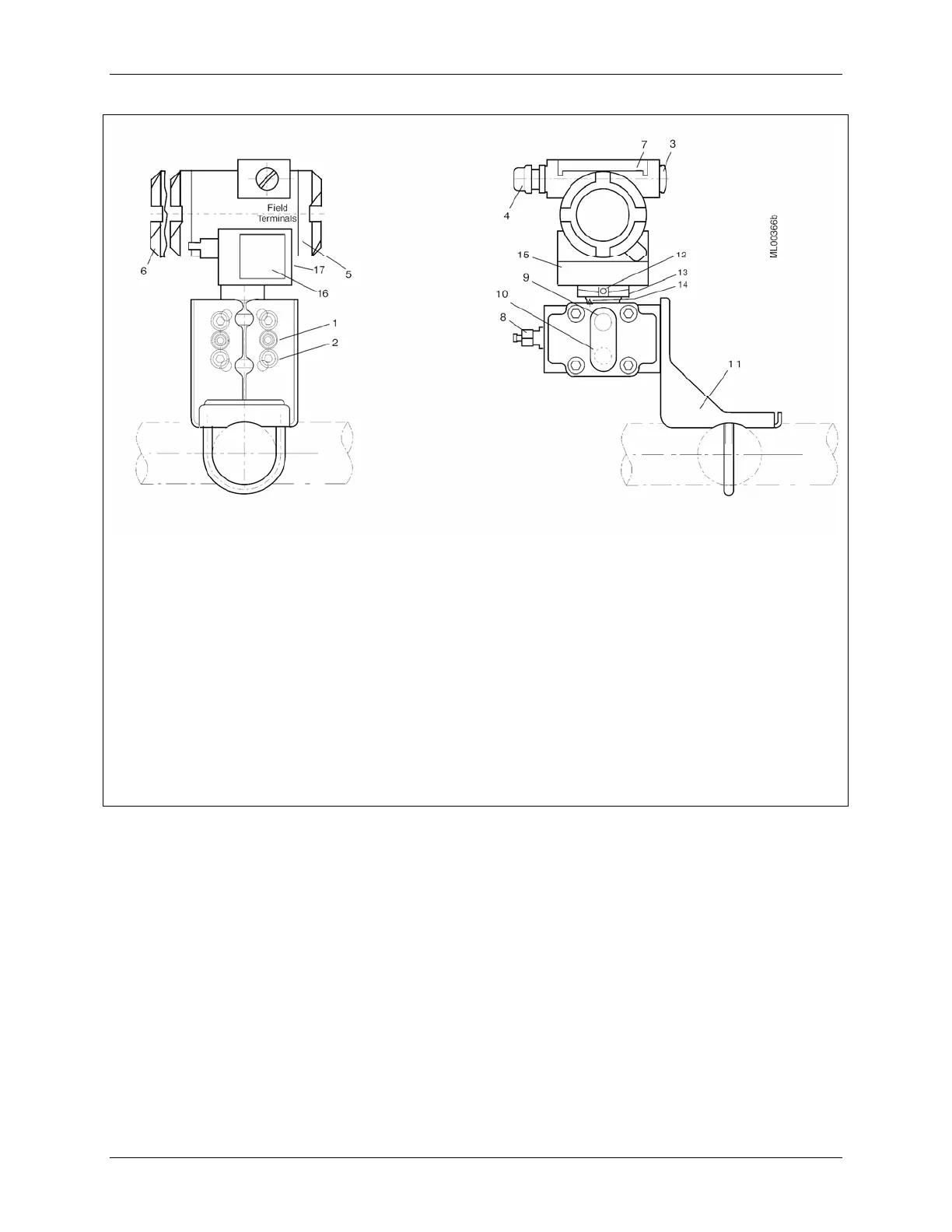
Process Connection 1/4-18NPT for absolute
pressure + side
Mounting thread M10, M12 or 7/16-20UNF
Blanking plug
Electrical connection:
Screwed gland M20 x 1.5
Screwed gland 1/2-14NPT
Field terminals; remove enclosure cap for
access
Electronics module and display; remove
enclosure cap for access
Hinged access cover over magnetic
pushbuttons
Sealing screw
Side vent for measuring liquid
10
11
12
13
14
15
16
17
Side vent for measuring gas (supplement H02)
Mounting bracket, optional
Enclosure setscrew
Enclosure rotation limits (see 14 reference
arrow)
Enclosure rotation reference arrow; see
Section 4 for details
Tag plate
Approval plate; Rating plate on other side
Enclosure ground screw
This Figure is for Models 7MF4333, 7MF4433,
and 7MF4533.
FIGURE 1-2 Differential Construction; Differential, Flow, and Absolute Models
 Loading...


