Circuit Description UMSITRPDS3-1
November 2005
8-4
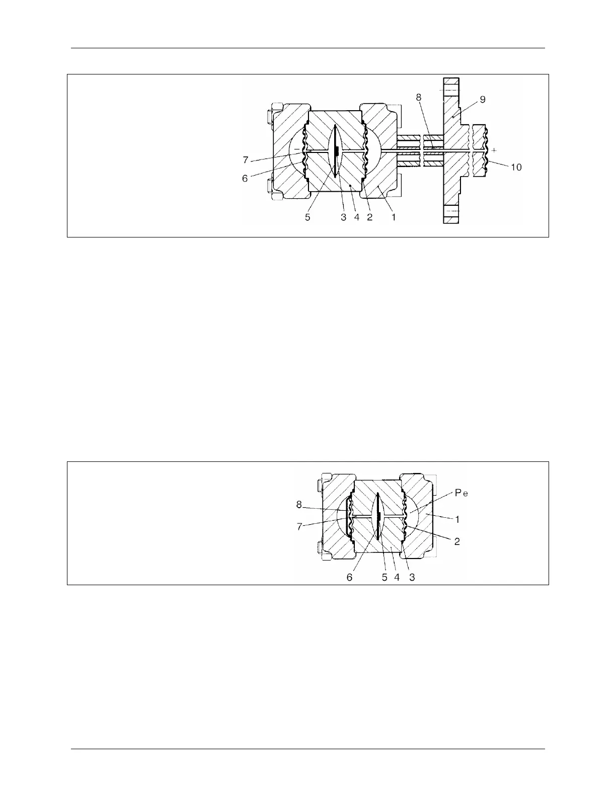
1
2
3
4
5
6
7
8
9
10
Process flange (qty. 2)
O-ring (qty. 2)
Silicon pressure sensor
Measuring cell body
Overload diaphragm
Seal diaphragm at the
measuring cell (qty. 2)
Fill fluid
Capillary tube with fill
fluid
Mounting flange with
capillary tube
Seal diaphragm at the
mounting flange
FIGURE 8-4 Flanged Level Measuring Cell
8.5 ABSOLUTE PRESSURE (DIFFERENTIAL CONSTRUCTION)
Absolute pressure p
e
is transferred via the seal diaphragm (2) and the fill fluid (7) to the silicon pressure
sensor (5). The pressure difference between the input pressure (p
e
) and the reference pressure (8) on the
low pressure side of the measuring cell flexes the measuring diaphragm. Four piezo-resistors in a bridge
circuit grown on the measuring diaphragm change their resistances in response to the change in applied
pressure. The change in resistance causes a bridge output voltage change that is proportional to the
absolute pressure.
If measuring limits are exceeded, the overload diaphragm (5) will deflect until the seal diaphragm comes
into contact with the body of the measuring cell (4) protecting the silicon pressure sensor (5) against the
overload.
1
2
3
4
5
6
7
8
p
e
Process flange (qty. 2)
Seal diaphragm at the
measuring cell (qty. 2)
O-ring (qty. 2)
Measuring cell body
Silicon pressure sensor
Overload diaphragm
Fill fluid
Reference pressure
Input variable pressure
FIGURE 8-5 Absolute Pressure Measuring Cell, Differential Construction
8.6 ABSOLUTE PRESSURE (GAUGE CONSTRUCTION)
Pressure p
e
is applied via the seal diaphragm (3) and full fluid (4) to the absolute pressure sensor (5). See
Figure 8-6. This flexes the measuring diaphragm on which four piezo-resistors in a bridge circuit have
been grown. Bridge resistance will vary with the applied pressure to generate a bridge output voltage that
is proportional to the input pressure.
 Loading...


