Installation UMSITRPDS3-1
November 2005
4-12
MG00350a
+
_
- +
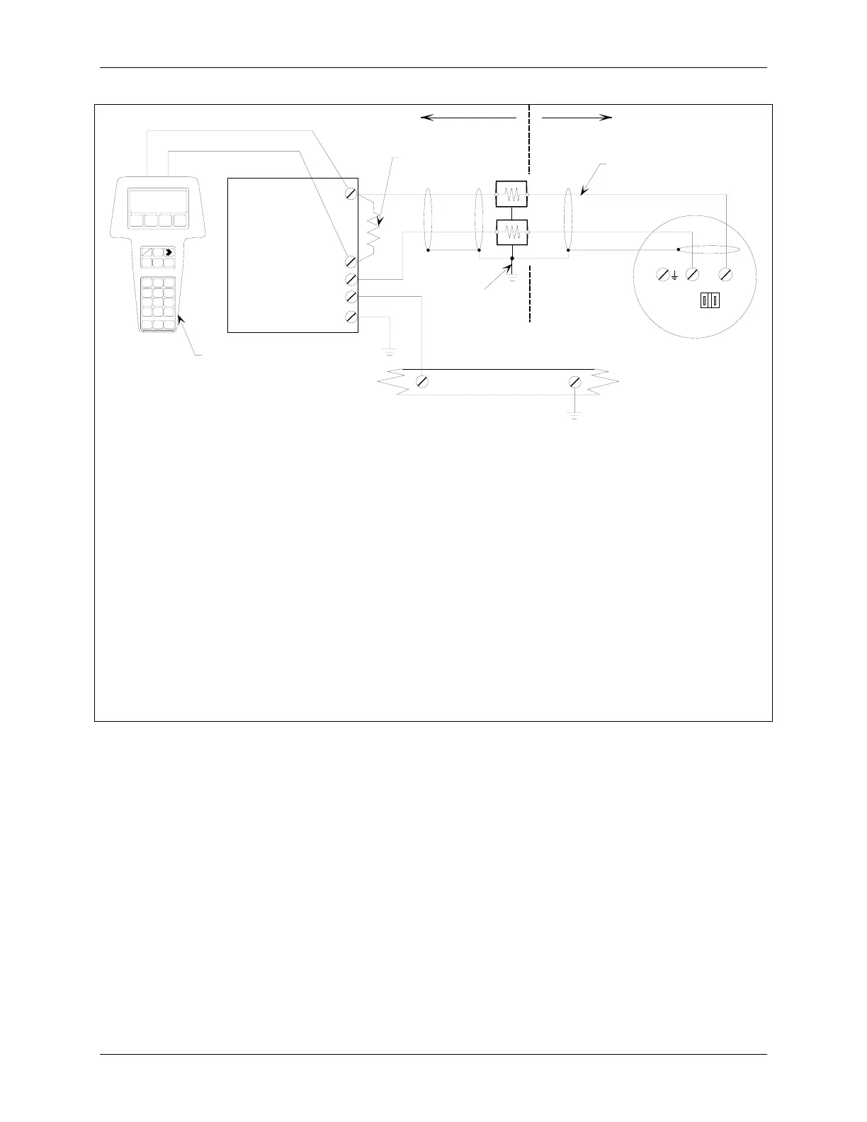
4-20 mA
Hazardous
Location
Non-Hazardous
Location
Procidia
Terminals
AIN1
See Note 4
34
I
O
Transmitter
Terminals
See Note 5
250
See Note 1
See Note 2
See Note 6
See Note 3
35
18
GND
33
Common Ground Bus
1. Minimum network resistance equals the sum of the barrier resistances and the current sense resistor. Minimum
value is 250 Ohms; maximum value is 1100 Ohms.
2. Connect the HART Communicator as shown in Figure 2-2 for hazardous and non-hazardous locations. The
HART Communicator is a non-polar device.
3. Supply and return barriers are shown. Interconnect all cable shields and ground only at the barriers.
4. Procidia terminal assignments are:
• 34 – Analog Input 1 +
• 35 – Analog Input 1 Common
• 33 – 24 Vdc
• 18 – Station Common
5. For access to transmitter field terminals, remove the enclosure cap.
6. Maximum cable length is as calculated using the formula in section 4.3.6.
FIGURE 4-7 Procidia to Transmitter Connections (Analog Mode)
 Loading...


